Hello,
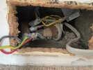
I am in the process of moving a few sockets out of the skirting board. I have done a few of them already, but uncovered a bit of a mess on this one (see picture below). This is on a ring main and there is a single socket exactly on the other side in the adjoining room, which I have moved up 2 weeks ago. I've already noticed these loose terminal blocks last week, but wanted to clean these up only now as I have better access from this side where I have a double socket.
- The two wires coming out the left and right side were connected to the socket [1&4]
- [5,2,3] all connect at these push-fit connectors
- [3] also has old cable colours, so I suspect that is the part of the original ring main going back down
- [5] is a single wire going up to the single socket in the adjoining room. When I moved that socket up I ran a new cable up and joined them with a Wago JB and terminals, simply replicating existing wiring
- [2] runs as single cable under the floorboards to another wall where there is another double socket
I do not want to rip open the floorboards are re-wire everything to make "clean" ring, but I also do not want to leave these wires the way they are. What would you recommend? Apart from using proper earth sleeving, new connectors and putting everything in a maintenance free JB.
The way I see it I could:
1. Keep as is and just clean up that wiring and stick everything inside a JB, then I effectively have one double socket on the ring main and a nearby JB, which feeds two other sockets, but not as spur on a spur
2. Connect this socket with [1] ordinary as ring and then continue via [5] up to the single socket in the adjoining room, run a second wire back down continuing the ring, which then goes into a JB. This JB then would feed the single cable under the floorboard to the other socket and also continues the wire back down. Is there any benefit in doing this and slightly cleaning up the ring?