Switched live misidentified - Danger?

Joined
16 May 2024
Messages
7
Reaction score
0
Country
United Kingdom
So rule one of taking a photo pre light removal was not done. First Lighting DIY project. Wont make the same mistake again.

I Replaced 2 ceiling lights (Kitchen and diner) assumed it was easy.
The wires identified are noted in the image below.
The lights had multiple live (Red) and what I assumed neutral (black) (before discovering what a switched live was)
So I attached lives to the "L" port on the lights. and Neutrals to the "N" Port. Earth to the earth port. (Excluded from diagram)

Worked fine before. But now the living room light doesnt come on (didnt change this light)
And for some reason the living room light switch turns both the kitchen diner lights on and off.
The kitchen 2 gang does nothing. But I can tell the feed runs from living room switch through the kitchen switch to the lights. (taking out bridge kills the whole thing)
I dont know which light is first or last in the sequence.

I assume some of the neutrals I put in the neutral ports on the lights. Were infact switched lives and now the kitchen switch is bypassed?.

Is this dangerous to play around with? I purchased a mulitmeter and am awaiting extended wires so I can find out where these wires start and end.
Oddly there are black wires leaving the lights. But all red at switch.
I'm confused... any advice? Am at risk of starting a fire when turning these on currently?

What you see below is all I see. Wires going to lights from ceiling and leaving switch

Light setup.png
 
Last edited:
Sponsored Links
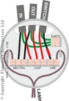
1715853885082.pngStandard ceiling rose wiring. Real life looks like this
1715853939136.jpeg
arrows show cable hooks and there are pictures all over the internet about the British system. The basic idea is we have both switched and permanent line at the ceiling rose, so emergency lighting and ceiling fans are easy to wire into the system, and the cables runs are kept short so reduced volt drop, however many other countries do not follow the same system. They use the switch back box as a junction box instead, there are pros and cons for both systems, lack of neutrals at the switch can today be a problem when wanted to use smart switching.

There is only one colour which shows what the wire is, green/yellow shows earth, it is not practical to colour all wires with one colour to show voltage, it would make tracing hard, so better to sleeve the wires to show what they do, but clearly sleeves can fall off.

We have four basic light switches, on/off (one way), change over (two way), reversing (intermediate), and two pole. Today we also have all the smart switches, relays, and bulbs as well, which includes methods to dim lights, this has resulted in many options in wiring, however the standard wiring for lights and sockets was developed near the end of the second world war in the UK and we still use the same basic layout.

I would suggest you google "Flameport" he has a whole host of videos on youtube, which are very good. There is no point in re-inventing the wheel, and writing out an instruction set when he does it so well.

Photos of the ceiling rose and switches may help, I can post a diagram,
two-way-real.jpg
one shown is two way wiring, but these are all over the internet, so try with photos of what you have now.
 
Edited to change images**

Thank you for the info. I will for sure look at the videos after work. and also take photo of lights and switch

The ceiling lights i use dont have the same 3 rows of ports as the image you included.
Perhaps because mine are 3 and 4 spotlight fittings rather than one bulb?

They look like this:
1000049494.jpg


Switch looks likes this.
1000049487.jpg


The lighs will follow later:
One light has 1 red, 2 black and an earth
The other has 2 red, 2 black and and 2 eath
Oddly the red and earth are together in a sleeve, the blacks are seperate.

The living room switch that must run though this and now powers kitchen lights, looks like this:
1000049489.jpg


The diagram I initially posted shows the wites leading from ceiling to the lights. Im sure one or more of the black must be a switched live and therefore need to be in a live port on the light? Not the neutral?

Thanks (light inages to follow)
 
Last edited:
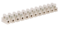
The first picture is a common sight, I just change the block connector for one with 4 terminals. Not seen that ceiling rose, but pre-war they would likely have been like that. I am only 73 so don't remember that far back.

It says taken 3 October 2020 and there is a fee of £35 payable for using it. So suggest you remove it. Want to see your stuff, not some random photo.
 
Sponsored Links
The first picture is a common sight, I just change the block connector for one with 4 terminals. Not seen that ceiling rose, but pre-war they would likely have been like that. I am only 73 so don't remember that far back.

It says taken 3 October 2020 and there is a fee of £35 payable for using it. So suggest you remove it. Want to see your stuff, not some random photo.
Thanks, images updated, lights will follow later tonight after work but initial diagra. may explain the wires leding from ceiling to them
 
Last edited:
1715860250557.png
To work out which blue is line and which are neutral is not easy. Both line and neutral are considered live, yes I know confusing, I did not make the rules. So with three cables coming to a ceiling rose, I would normally turn off power, and one by one clip my meter on buzzer range on the two wires from each cable and work the light switch until I find the pair where buzzer turns on off, and then would put brown tape on that blue.

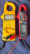
I carry this 1715860653166.pngin my tool bag, so easy enough to split out wires one wire per terminal so I can test with meter with no chance of in error touching a live wire, I carry one of these Clamp-meter-small.jpg to test with, they do so much, in theory should use a tester not having batteries or any switch to test for line, and also a proving unit, however I find I can get away with the clamp on for most jobs, and since it has no wired amp range, getting the selector switch in wrong place does not result in a big bang.

So what have you got to test with?
 
I have this:
With extra 10m wires on route as I assumed I need to clip one end to the wire in the switch (Power off) and test the other ends in the light until it beeps?
something about continuity setting?

since the wires in the switch were not tampered with. I assume I need to attach this to the wires in the L1 slots and then when I find the end at the light to match this, move it from neutral slot in the light fitting to the live? I find it strange how one light has 2 black an d 2 red. the other 2 black and only 1 red though. I assumed one black in each light SHOULD be in the neutral slot.

All i know right now is that there is a live feed running through both lights, through my 2 gang and into the 1 gang in another room. Somehow rendering the 2 gang useless as a switch.

1715861870203.png

Using the
 
How many lights are there in the kitchen? undercupboard lights?
 
How many lights are there in the kitchen? undercupboard lights?
2 lights total in kitchen; a dining room and a kitchen light.
Both wired from ceiling, they are 3 bulb units units. Each have ports for 2 Neutral, 2 live and 2 earth in the fittings.
One of those fittings has 1 red (and earth) and 2 black.
The other light has 2 red (and earth) and 2 black.
Kitchen has a 2 gang for what I assumed was for one each

The second room has 1 light and a 1 gang.
The one gang now controlla the 2 other lights.

Apart from all being red, 2 gang looks ok so im assuming issie is the black wires. As i take it red is always live. Where as black could be either and i have all blacks on neutral ports in the light fittings.
 
Well, whatever suits you!
Indeed, it is one of my arsenal of tools, I didn't bother getting any more of these out for the photo, nor my Robbin or Avo kit or the other two Beckmann's:
1715290584817.jpeg

However, bear in mind that I have seen some of these with leads that break if you bend them just a little.
In which case a comment warning of that danger is far more helpful than desciribing what I have found to be a very acceptable tester as garbage.

For what it's worth the leads that came with is are still in their sealed bag as I'm using those from its predecessor (which fell 45metres to a concrete surface:cry:... RIP).
 
Getting back to the lighting problem, are the new kitchen lights low power LED and the lounge much higher powered or a conventional bulb?
 
In which case a comment warning of that danger is far more helpful than desciribing what I have found to be a very acceptable tester as garbage.
I just don't trust meters that are sold by Amazon or ebay without any brand. I've got a similar cheap meter but that only stays in the car for 12v testing only.
 

DIYnot Local

Staff member

If you need to find a tradesperson to get your job done, please try our local search below, or if you are doing it yourself you can find suppliers local to you.

Select the supplier or trade you require, enter your location to begin your search.


Are you a trade or supplier? You can create your listing free at DIYnot Local

 
Sponsored Links
Back
Top