Thermostat wiring

Joined
2 Nov 2022
Messages
21
Reaction score
0
Country
United Kingdom
Hi All,

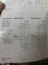
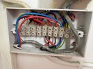
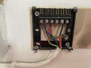
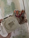
Could someone help me wire up my new smart thermostat?
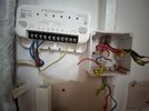
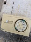
I’ve successfully removed the old wired thermostat and connect to internet etc.

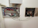
Just need help working the wireless receiver on my combi boiler.

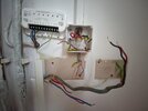
Photos of the stage I’m at currently.
 

Attachments

  • image.jpg
    image.jpg
    235.9 KB · Views: 181
  • 0FFF2C4D-D542-4EF3-A591-D2BC4822EF60.jpeg
    0FFF2C4D-D542-4EF3-A591-D2BC4822EF60.jpeg
    185.7 KB · Views: 164
  • 5548D8B6-0BF8-497B-B4B0-B77EFBAE54F8.jpeg
    5548D8B6-0BF8-497B-B4B0-B77EFBAE54F8.jpeg
    169.4 KB · Views: 199
Sponsored Links
Photos of how the old setup was.
 

Attachments

  • 23C17B6B-CC04-423A-A0AB-7DD5E71055E2.jpeg
    23C17B6B-CC04-423A-A0AB-7DD5E71055E2.jpeg
    253.9 KB · Views: 102
  • 5D3EA9C8-EFEE-4CB7-B0C5-45738ED7E776.jpeg
    5D3EA9C8-EFEE-4CB7-B0C5-45738ED7E776.jpeg
    300.7 KB · Views: 123
  • 5D0790E8-D192-4D80-887E-E505DFDD33B2.jpeg
    5D0790E8-D192-4D80-887E-E505DFDD33B2.jpeg
    278.4 KB · Views: 86
That won’t work as you’ve wired it incorrectly. Are you using the same wiring as this?

1669824459677.jpeg
 
Sponsored Links
At the moment you appear to have connected the live and the neutral to the controller switch. God job it isn't working otherwise BANG!

Capture.JPG


You also appear to have connected the heating control wires (black wires with red sleeves from the picture below) in the to the N & L terminals. Which fortunately has prevented it the controller operating and producing the aforesaid 'bang'.

So to change this:

Capture1.JPG


To the new controller:

The blue wire in N....goes to the new controller N
The brown wire in L....goes to the new controller L
The black wire with red sleeve in 1....goes to the new controller Central heating COM
The black wire with red sleeve in 3....goes to the new controller Central heating NO

I assume you have a combi boiler and no attached hot water cylinder. If so, the above is all you need to do. No need to change anything else. If you had a separate room thermostat and programmer, the one that is still insitu should be set to be permanently on. If you had a programmable thermostat that had both time and temperature control you can ignore this.

As per @CBW, No idea what the other wires do now you have disconnected them. But they should probably go back as they were.
 
Thanks for the replies.

Stem - very helpful and of course I never switched any electrics on while this is in progress.
Correct on the assumptions that we have a combi boiler without a HWC.

We had a wired thermostat with temperature on only which I have removed and blanked off as per the instructions given with the new thermostat.
The photo above with the black casing held a manual ticking timer box which I removed to show the proposed wiring.
Can get a photo if it’s needed.

So if I reset EVERYTHING to how it was before I touched anything and then make the changes to the new controller as you say above would that do the trick?
 
This type of backplate is associated with both thermostats and programmers. If the thermostat (or thermostat receiver) was on the front of this, then yes, that's all you need to change.

Capture1.JPG


However, If the thermostat was wired in elsewhere, what product was on this backplate, and what happened to the old thermostat.
 
Here is the thermostat which was wired in downstairs.
 

Attachments

  • 330D0E2F-88F6-4821-B583-4D8AD0B155F8.jpeg
    330D0E2F-88F6-4821-B583-4D8AD0B155F8.jpeg
    268.7 KB · Views: 69
This was on the backplate. I still have everything that was removed.
 

Attachments

  • 5C9EA3AE-3FE2-43C6-AB3C-BB164C107990.jpeg
    5C9EA3AE-3FE2-43C6-AB3C-BB164C107990.jpeg
    313.8 KB · Views: 32
OK, then the new controller can replace the timer backplate as earlier.

The old room thermostat can be left in place and set to maximum to stop it interfering with the new controls, which is the easiest way for a novice. Or, if the old thermostat is removed, its live switching wires need to be linked together to complete the circuit, otherwise the wiring will remain 'open circuit' and the heating won't work.

Your thermostat looks like a Drayton RTS1. If so, the wiring diagram is:

Capture.JPG


The wires that were removed from terminals L and 3 would need to be joined together to complete the circuit and the neutral wire isolated safely. If this is done where the thermostat was located, a visible terminal box should be used to indicate the presence of the live wires and connectors.
 

DIYnot Local

Staff member

If you need to find a tradesperson to get your job done, please try our local search below, or if you are doing it yourself you can find suppliers local to you.

Select the supplier or trade you require, enter your location to begin your search.


Are you a trade or supplier? You can create your listing free at DIYnot Local

 
Sponsored Links
Back
Top