Thorn Olympic 38/50B replace programmer with Siemens RBW2001

Joined
25 Nov 2017
Messages
7
Reaction score
0
Country
United Kingdom
Hi All

Looking to replace the Smiths clock that came with the boiler with a siemens rwb2001

It's a pumped Central Heating Gravity Hot Water system.

From looking at other posts it looks like it's best to take the outlets from the old timer and migrate them to the new one from the connector block inside the boiler.

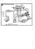
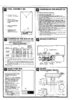
Looking at the wiring diagram I'll need to hook up Live Neutral and pins 3 and 4 as per this pdf

https://www.downloads.siemens.com/d...spx?pos=download&fct=getasset&id1=A6V10464887

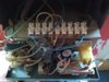
Just looking for confirmation. I can take pictures later on today once I get to see inside the existing wiring loom.

Thank you
 
Last edited:
Sponsored Links
The RWB is wired as below:

Capture.JPG


So, you are correct about the wiring terminals to use:

N & L are required to provide it with power. This should come from the same 3A supply as the boiler
Terminal 3 Hot water on will be connected to the boiler
Terminal 4 Central Heating on will be connected to the pump, via the room thermostat if you have one.

On the back of the RWB is a switch marked 'G' for gravity hot water and 'P' for fully pumped. You should set this switch to 'G' for your installation and follow the reset procedure in the manual after doing so.
 
Thank you stem for taking the trouble to reply, much appreciated.

I'll follow up with pictures so that it's a complete thread for anyone else trying to figure out a similar replacement.

Bryan
 
Hi Again

I found the following wiring diagram for the boiler, I was going to use the existing connector block to hook everything up as per the bottom right diagram - number 28

I'll discover more when I open the boiler up, but this has three wires hooked up as well as live and neutral.

I'd be grateful if you wouldn't mind commenting on this. I'm guessing it's because the RWB2001 has independent hot water and central heating switches which the original doesn't
 

Attachments

  • myson-programmer-wiring.jpg
    myson-programmer-wiring.jpg
    353.6 KB · Views: 133
Sponsored Links
I have to confess that I haven't worked on one of these as they are rather old, so can't offer any personal experience. However, if you take the programmer wiring as per your post...

timer.JPG


...you can see that the programmer is connected to a L & N supply, and provides 3 control signals back in return:

Heating 'on' (connected to boiler terminal 2)
Heating 'off' (connected to boiler terminal 3)
Hot water 'on' (connected to boiler terminal 4)

As well as requiring a L & N, those same three control signals are available from the RWB

rwb.JPG


Heating 'on' (4)
Heating 'off' (2)
Hot water 'on' (3)

However, as you have gravity circulation of hot water and pumped central heating, you will not be able to have the central heating 'on' without the hot water being 'on' also. This is a restriction of the plumbing not the controls. I seem to remember that some RWB programmers have a selector switch at the back marked G (gravity) and P (Pumped) which would be set to G for your system. This makes sure the hot water is turned on automatically whenever the heating is selected on.

However if your programmer doesn't have this switch, you will have to make sure that the set 'heating on' times, correspond with the 'hot water on' times.
 
Hi Stem

It does have that switch for Gravity and Pumped, and thank you so much for taking the trouble to reply again. It looks like it's set for gravity at the factory.

Thanks one again.

Bryan
 
Last edited:
I seem to remember, (but I might be wrong) that there's a sequence of events to follow when moving the switch from one position to another, otherwise it doesn't take effect. If you have the instructions they should tell you.
 
Hi stem

I have all the instructions to hand that came with the physical switch itself and things I've gathered online. The Gravity Pumped switch on the back isn't desperately clear as it's recessed, but I'm going to be double-checking that physically anyway.

The main thing is I've had your response telling me clearly what I need to know, which I'm really grateful for and I'm happy that it'll all work fine.

I'll post up the results once it's running on the new controller :)

Cheers

Bryan
 
Managed to get a picture of the insides today - all as expected
 

Attachments

  • boiler-insides.jpg
    boiler-insides.jpg
    153.2 KB · Views: 155
...and here we have a list of components that hook up to the main connector, so that we have a complete wiring picture from start to finish...

Just need to get some proper hook up cable, and give it all a whirl
 

Attachments

  • boiler-components-wiring.jpg
    boiler-components-wiring.jpg
    134.4 KB · Views: 153

DIYnot Local

Staff member

If you need to find a tradesperson to get your job done, please try our local search below, or if you are doing it yourself you can find suppliers local to you.

Select the supplier or trade you require, enter your location to begin your search.


Are you a trade or supplier? You can create your listing free at DIYnot Local

 
Sponsored Links
Back
Top