Three-phase system - circuit allocation

Joined
3 Aug 2011
Messages
10
Reaction score
0
Country
United Kingdom
Building a new flat, and the power supply is 3 phase 3X25A.

My contractor changed the electrician half-way through the job. The previous electrician was going to wire all the phases together (to my understanding in effect simulating a 75A connection) The new guy is a bit of an #$@%, allocated the circuits to phases and refuses to explain how he allocated them (about 15 circuits) between phases, on the basis that he'll be available (at a fee I presume) to sort things out later.

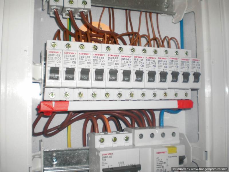
Setting aside the attitude for a moment, I have usually handled home electrics myself - I am however familiar with older homes. In this case, in the consumer unit the allocation is carried out via an "allocation strip" (?) - I am unfamiliar with these.

I want to be able to reallocate circuits myself (if I suddenly find that the kettle, the washer and the dryer are placed on the same 25A phase, for example) - if anyone can point me to an information source on this this method of allocating circuits, I'd be glad. Have not managed to find anything myself... If this is not a common item, I'll post a pic.

Thanks

D.
 
Sponsored Links
In this case, in the consumer unit the allocation is carried out via an "allocation strip" (?) - I am unfamiliar with these.

I'm not absolutely certain of the exact arrangement in your particular unit, but it sounds as though it's probably just a flexible busbar arrangement which allows the fitted MCB's to be split between the phases by rearranging the busbar links somehow. Are all the MCB's in one line? Some photos would certainly help.
 
Hi

I can explain whats going on, to help you understand and not get ripped off.
You should not be playing about with this stuff if you do not know what you are playing with.

First the voltage between phases. If it based on U.S. it will be 220v or so, with phase to ground 110v. Assuming that, then.

The phases are all at different phase angle volts and will blow if any two touch. The original guy could not have joined them together, if the main breakers did not trip.

Each phase supplies an individual bus bar in the main box.

Individual circuit breakers then take power from each of these bus bars.

Lights and small stuff will be one breaker and 110v sub circuit.

Bigger stuff will have a double pole breaker and run at 220v. Taken off two different phase bus bars.

The bus connections are normally PHase 1 PH2 PH3-- PH1 PH2 PH3-- etc in adjacent order.

If you switch off a breaker, that circuit will go dead. This will show whats controlling what. If you switch off a fridge or freezer leave it 5 min before switching it back on.
You should not be unplugging breakers from the bus bars if you do not understand the danger.

If you switch everything in the house ON and the main breaker holds then the new guy has balanced the load across the three phases. Job done

No need for you to poke about if there is no tripping occuring

Mike
 
If it based on U.S. it will be 220v or so, with phase to ground 110v.

You don't get a 2:1 ratio with a 3-phase supply. The normal U.S. supplies in this range are 120/240V (or thereabouts) single-phase, or 120/208V three-phase.

But I believe that Israel has 230/400V 3-phase supplies anyway, although possibly with some older 127/220V systems modeled on those used in Europe.
 
Sponsored Links
Thanks for the replies.

Attached is a pic - after asking around a but more, I found out that (as MikeR said) it is indeed a bus bar which allocates circuits to phases on a consecutive basis.

I am not happy leaving this as is - firstly as it's my house I want to know what's connected to what OK, simple job using a radio plugged into each socket).

Secondly,remember, he didn't know which circuit is which - simply connected the wires left in the distrib board by his workers - and the chances of him getting it right by chance are not zero but pretty close. There is a substantial load if everything really does work together (~ 70 A or so, not all of it installed yet )and I want to plan this myself instead of having breakers tripped and then going back to figure out how it's put together.


It's a little difficult to see exactly how the supply busbars are arranged, whether in sequence A-B-C-A-B-C etc. or whether they're grouped together in some way, e.g. A-A-A-B-B-B-C-C-C etc.

Could you take another picture with the busbar cover removed? (The white trim which has red tape around the ends.)
 
Back
Top