Two door bells on one push button switch

There's no illumination in the push button.

I've looked and I can't see a 2 pole push button switch for door bells. Do they even exist ?
 
Sponsored Links
There's no illumination in the push button.
In that case, I suppose you could theoretically probably get away with the 'crazy' approach (transformer secondaries and bells both in series, per BAS's diagram)
I've looked and I can't see a 2 pole push button switch for door bells. Do they even exist ?
I have to say that I haven't come across one - but nor have I ever had a need to look for one. There are undoubtedly plenty of DP push switches out there, but most would probably not be suitable for use as a bell push.

Kind Regards, John
 
To be clear on what I intended.

Only the 6v bell push button circuits in series so they can be operated from a common door bell switch.


The mains feed to the bells must of course be a standard mains feed. I would perhaps take a local feed from lighting circuit near to the new bell unit.
 
In that case, I suppose you could theoretically probably get away with the 'crazy' approach
PLAN B

Stop trying to pursue the crazy idea of cobbling together a solution simply to hang onto a £20 door chime and put a dual-sounder system in which is properly designed.
 
Sponsored Links
To be clear on what I intended. Only the 6v bell push button circuits in series so they can be operated from a common door bell switch.
I'm not totally clear as to what you mean. As I said, if you wanted to take that approach (the one he called 'crazy') you would have to wire it as per the diagram that BAS posted.
The mains feed to the bells must of course be a standard mains feed. I would perhaps take a local feed from lighting circuit near to the new bell unit.
Sure, and that relates to the 'primary' (230V) sides of the transformers, which would obviously be wired (to the mains) 'in parallel'. To do as BAS was depicting, it's the 'secondary' (6V or whatever) sides of the transformers which would have to be wired in series (and 'the right way around' for it to work).

Kind Regards, John
 
PLAN B ... Stop trying to pursue the crazy idea of cobbling together a solution simply to hang onto a £20 door chime and put a dual-sounder system in which is properly designed.
Clearly the ideal, but it's a choice that only the OP can make. ... and, of course, it was you who posted a diagram of a 'cobble' that. AFAICS, would actually work for the OP - and, had you not done that, we probably wouldn't even be discussing that possible approach :)

Kind Regards, John
 
I've decided to invest in a new twin bell system, possibly wireless.


My apologies to all for wasting your time with the posting but thanks for the informative replies.
 

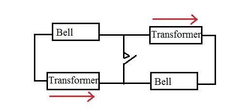
Will work provided both transformers have the same output voltage and are connected with the phases of their outputs as shown. Anti-phase

When the bell button is NOT pressed the voltages from the transformers cancel each other and no current can flow.
 

Will work provided both transformers have the same output voltage and are connected with the phases of their outputs as shown. Anti-phase

When the bell button is NOT pressed the voltages from the transformers cancel each other and no current can flow.


The new bell is 6V, so the old bell would need to be 6V also as I understand?

From your diagram for the push button connections, need basically to be the opposite of each other?
 
Yes both bells and their transformers would need to be the same voltage and as you already have a 6 volt bell then the new one will need to be six volts.
 
Thanks

To reiterate what you say, the wires from the bell push need to be the opposite in each bell ?


Have you done this this kind double bell installation yourself?
 
Will work provided both transformers have the same output voltage and are connected with the phases of their outputs as shown. Anti-phase ... When the bell button is NOT pressed the voltages from the transformers cancel each other and no current can flow.
True - but as you say, that functioning is fairly crucially dependent on the voltage outputs of the two transformers being identical, which may not necessarily be the case. In contrast, putting both transformers (in-phase) and both bells all in series (per BAS's diagram) would not be critically-dependent on anything.

Kind Regards, John
 
May I just ask regarding the diagram, as the bells and transformers are wired in a closed loop, why would the switch have to close for the bells to operate when the circuit is already closed ?
 
May I just ask regarding the diagram, as the bells and transformers are wired in a closed loop, why would the switch have to close for the bells to operate when the circuit is already closed ?
Because, as bernard said, the transformers are wired such that when the loop is closed, their voltages are 'opposite' and therefore cancel out - just as if you put two identical batteries in series with the positive of one connected to the positive of the other. However, for the reason I recently gave, I would not personally favour bernard's arrangement, since it relies on the voltages from the two transformers being identical for them to perfectly 'cancel' in the closed loop. 'Clever' though bernard's idea is, the system in BAS's diagram would IMO be more 'foolproof'.

Kind Regards, John
 

DIYnot Local

Staff member

If you need to find a tradesperson to get your job done, please try our local search below, or if you are doing it yourself you can find suppliers local to you.

Select the supplier or trade you require, enter your location to begin your search.


Are you a trade or supplier? You can create your listing free at DIYnot Local

 
Sponsored Links
Back
Top