

Hi evryone and please help.
I have an existing worcester 280rsf boiler that has worked fine for years and I want to install a remote wireless room thermostat (honeywell cm927 or similar) but I am unsure of the wiring. At the moment the boiler is either on or off and I want more control.
The existing system is as follows
A fuse to a programmable digital timer and then a 5 core wire from the timer to the boiler
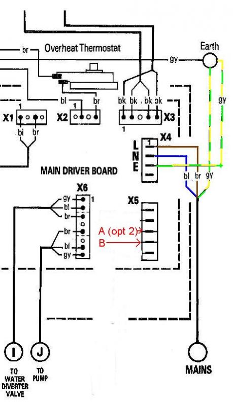
Inside the boiler the Brown is connected to the top terminal of block X4 (I will call this 4)
The Blue is connected immediately below (3)
The Green yellow is connected to the bottom terminal (1)
Another Green yellow comes out of terminal (2) to earth but nothing goes in. Is this correct?
The other 2 wires are black and go to block X5 both are routed to terminal (2) of this block second from bottom and I assume this is the link i have read about. It is in the section labelled room stat and has three terminals in this section.
Two more terminals (above) are also in this block X5 labelled frost stat and are not in use
So how do I wire up the honeywell receiver? which i have not bought yet!
I also have rad valves some in use some not but that is another problem for another day
Please help in simple terms if you can
thanks
dave
I have an existing worcester 280rsf boiler that has worked fine for years and I want to install a remote wireless room thermostat (honeywell cm927 or similar) but I am unsure of the wiring. At the moment the boiler is either on or off and I want more control.
The existing system is as follows
A fuse to a programmable digital timer and then a 5 core wire from the timer to the boiler
Inside the boiler the Brown is connected to the top terminal of block X4 (I will call this 4)
The Blue is connected immediately below (3)
The Green yellow is connected to the bottom terminal (1)
Another Green yellow comes out of terminal (2) to earth but nothing goes in. Is this correct?
The other 2 wires are black and go to block X5 both are routed to terminal (2) of this block second from bottom and I assume this is the link i have read about. It is in the section labelled room stat and has three terminals in this section.
Two more terminals (above) are also in this block X5 labelled frost stat and are not in use
So how do I wire up the honeywell receiver? which i have not bought yet!
I also have rad valves some in use some not but that is another problem for another day
Please help in simple terms if you can
thanks
dave
 )
)