• Looking for a smarter way to manage your heating this winter? We’ve been testing the new Aqara Radiator Thermostat W600 to see how quiet, accurate and easy it is to use around the home. Click here read our review.

Wiring a fan isolator switch

Joined
23 Sep 2024
Messages
10
Reaction score
2
Country
United Kingdom
Hi everyone,

I hope somebody can help me see something obvious.

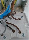
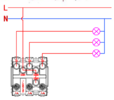
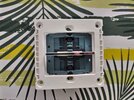
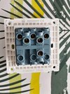
I have bought a fan isolator from Trendi (for aesthetic reasons) and I would like to replace the existing one; the problem is that I do not understand how to wire it, because the new switch has a different layout for the terminals. The instructions only managed to confuse me even more.

I have included a photo of the existing switch and the diagram provided in the instructions. Where does each cable go?

Thank you in advance
 

Attachments

  • IMG_20250821_123716_hdr.jpg
    IMG_20250821_123716_hdr.jpg
    130.8 KB · Views: 67
  • Screenshot 2025-08-21 124605.png
    Screenshot 2025-08-21 124605.png
    118.4 KB · Views: 56
Ignore the new diagram.

Label the wires before you disconnect anything.

You have 3 pairs of wires.

On the old switch, they are labelled L1-L1, L2-L2, and N-N.

On the new switch, they are labelled COM1-L11, COM2-L21, COM3-L31.
 
Is the new one a 3 gang light switch?

From the back it looks like one, but the bottom terminals are blanked out. The front though has one single big switch (see photos).
For completeness, here is the link to the product page on the website: http://trendiswitch.com/10a-triple-pole-bathroom-fan-isolator-switch-1130-p.asp (apologies if including the link breaks the rules of the forum)


Ignore the new diagram.

Label the wires before you disconnect anything.

You have 3 pairs of wires.

On the old switch, they are labelled L1-L1, L2-L2, and N-N.

On the new switch, they are labelled COM1-L11, COM2-L21, COM3-L31.

Thank you, that is very clear and helpful.
 

Attachments

  • IMG_20250821_135139_hdr.jpg
    IMG_20250821_135139_hdr.jpg
    267.3 KB · Views: 43
  • IMG_20250821_135133_hdr.jpg
    IMG_20250821_135133_hdr.jpg
    249.4 KB · Views: 41
1755856697289.png
Yes, the instructions are bad, but you have two cables each with grey, black and brown, and I have marked terminals also grey, black and brown, it does not matter brown goes in which hole marked brown, same with grey and black. Does that make more sense?
 
View attachment 390548 Yes, the instructions are bad, but you have two cables each with grey, black and brown, and I have marked terminals also grey, black and brown, it does not matter brown goes in which hole marked brown, same with grey and black. Does that make more sense?

Thanks @ericmark
I had assumed that this was the way to wire it, but the instructions made me doubt myself.

I have wired the switch yesterday thanks to edecotp's reply, but your response, I am sure, will be very helpful to anyone who stumbles upon this post in future.
 
The instructions are wrong. They show the way to wire it if it were a 3-gang lighting switch. They need different diagram for the assembly to be used a s a 3-pole fan isolator. Write and tell them. It won't do any good. but may make you feel better.
Yes, you're spot on, until I saw the picture of the back of the switch, I was not even sure if the switch would work, very poor instructions.
 

If you need to find a tradesperson to get your job done, please try our local search below, or if you are doing it yourself you can find suppliers local to you.

Select the supplier or trade you require, enter your location to begin your search.


Are you a trade or supplier? You can create your listing free at DIYnot Local

 
Back
Top