Wiring bell box INT500s to scantronic panel

Joined
16 Jan 2024
Messages
8
Reaction score
0
Country
United Kingdom
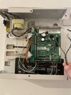
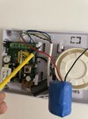
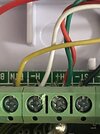
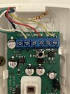
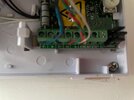
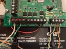
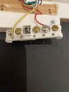
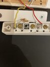
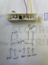
Hi all, telecoms engineer by trade but usually middle my way around most things…:) I’m trying to wire up a INT500s Internal alarm bell to a new scantronic 10 zone panel with I-ON10-KP. Please see the pictures of my installation and hoping one of you kind forum members can help me out. Also wired 3 x pir to the panel and would appreciate feedback if it’s done correct. I’ve read the “user guide” and engineers guide but to be honest the person that wrote it needs a boll****ing. Look forward to joining in with other to help also… cheers , Ian
 

Attachments

  • IMG_2613.jpeg
    IMG_2613.jpeg
    329.6 KB · Views: 58
  • IMG_2587.jpeg
    IMG_2587.jpeg
    223.8 KB · Views: 55
  • IMG_2585.jpeg
    IMG_2585.jpeg
    251.2 KB · Views: 52
  • IMG_2591.jpeg
    IMG_2591.jpeg
    295.6 KB · Views: 54
Sponsored Links
Sounder
+ and -
Bell output 1
Strobe output 2
Tamper return to TR ( you have it linked to 0v at the moment )
All these are on the bottom of the pcb
 
Pirs look ok
Cheers pal, I’m not there now for a few days so will test and get back to you all. Any telecoms, data, WiFi , broadband stuff I’ll repay the favour to you all…... Take it when you say sounder + and - you mean 12v and 0v connections….?
 
Sponsored Links
Hi Mark,
Going to do this tomorrow morning pal so just wanted to confirm the wiring colours so i don't blow the PCB on the alarm panel:

INT550s Scantronic panel

R- blue | ????????????? where does this go please
M- empty |
ST- black | OP2 (black)
H+ red and green twisted together | +12v (red and green)
H- white | -12v (white)
RTN yellow | TR (yellow)

Finally when the panel was shipped to me there is a little black jumper cable connecting TR to 0v as per the picture. Do i simply remove this jumper.

Cheer Mark,

Regards

Ian
 

Attachments

  • WhatsApp Image 2024-01-19 at 14.44.48.jpeg
    WhatsApp Image 2024-01-19 at 14.44.48.jpeg
    210.9 KB · Views: 30
  • alarm panel pic 1.jpeg
    alarm panel pic 1.jpeg
    354.9 KB · Views: 30
Yes when you wire in the int siren ( I hope you know it’s an internal unit ! ) when the tamper is closed you get 0v out of the yellow wire that goes to tamper return ( this is what the link is doing at the moment
 
Yes when you wire in the int siren ( I hope you know it’s an internal unit ! ) when the tamper is closed you get 0v out of the yellow wire that goes to tamper return ( this is what the link is doing at the moment
Yeah pal the alarms been fitted in an appartment and the internal bell is outside the appartment door. The old alarm was faulty so i swapped out for this as you can use the keyfobs on the keypad. Thanks for all your replies mark forums like this do work a treat when you’ve got decent lads on it
 
ADT came out to fix our alarm and instead of doing that, the engineer disabled the strobe lights which at the moment is the only deterrent I have! Does anyone know which wire I reconnect to get the lights working again?
 
Yes when you wire in the int siren ( I hope you know it’s an internal unit ! ) when the tamper is closed you get 0v out of the yellow wire that goes to tamper return ( this is what the link is doing at the moment
Hi mark, right alarm is up and working pal so cheers. I’ve done test walks throughout the property and each PIR works and picks me up. Managed to setup 4x prox tags too. Changed the walk out time to 20 seconds to arm. When i enter the property the first hall PIR picks me up and instantly sets the bell off……. I’m sure there will be a setting I’ve not done to delay the PIR’s picking me up before i present the Prox tag or enter my entry code….. any ideas????

Also I’ve only wired the front door contact as per the picture and it’s faulty(red colour on keypad) once I’ve disabled that zone on the keypad it returns to green. Do i need to attach 1 or 2 resistors within the door contacts for it to work also???? Cheers pal, regards Ian
 

Attachments

  • IMG_2654.jpeg
    IMG_2654.jpeg
    226.1 KB · Views: 19
Yes …it needs resistors or a multi contact with the resistors built in …this starts of your entry timer , any zones on the way to the keypad would be access or entry route ….depending on panel terminology….
 
Hi pal, right i terminated the resistors as per my picture and still getting a red error light on the key panel. I have set it to “not used” and tried to program the main entrance hallway PIR to do the job of the door contact but still triggers the alarm before i get change to swipe my fob to disarm. Can you point me in tv right direction for the correct wiring to get the door contact to turn green. Once that’s done can i then program that to “ entry route”…… cheers pal
 

Attachments

  • IMG_2963.jpeg
    IMG_2963.jpeg
    249 KB · Views: 16
As below ….there isn’t much room in those contacts and things can get shorted…
I would never use this type …either a multi version with built in resistors or elmdene QST -RD contacts
 

Attachments

  • IMG_3157.jpeg
    IMG_3157.jpeg
    197.4 KB · Views: 19

DIYnot Local

Staff member

If you need to find a tradesperson to get your job done, please try our local search below, or if you are doing it yourself you can find suppliers local to you.

Select the supplier or trade you require, enter your location to begin your search.


Are you a trade or supplier? You can create your listing free at DIYnot Local

 
Sponsored Links
Back
Top