correct way to wire up wireless room stat

Joined
14 Dec 2008
Messages
9
Reaction score
0
Location
Yorkshire
Country
United Kingdom
Hello there

I'm seeking advice on the correct way to wire up a Salus RT300RF thermostat. My boiler is an old Glow-worm model which had a standard type room stat wired in series on the live feed from the timer control to the boiler. This involved just the two wires - live and neutral. The earth wire was not employed and was just tucked away inside the room stat's casing.

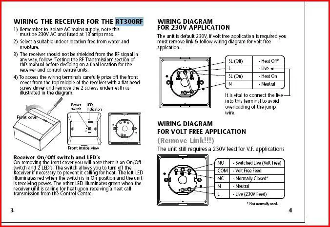
I'm a bit stuck on the correct way to connect the wireless receiver of the Salus. The instructions that came with it are confusing me (see picture).


I assume I should do it the 230v application way (top diagram). Is it a simple matter of connecting the live (red) feed from the timer to the connector marked L and the black wire to the connector marked SL?

This leaves the problem of the neutral connection at the bottom. The only wire that I have available is the earth wire. Should I use it as a neutral connection?

Any advice would be greatly appreciated!

Chris
 
Sponsored Links
If your current room stat only had 2 wires then its live in and live out(not neutral) regardless of colour of wires
 
If your current room stat only had 2 wires then its live in and live out(not neutral) regardless of colour of wires

Yes of course that's true!
I've now figured out how to add an image to a post so the picture is now showing properly.
I guess the main issue is how to make that neutral connection. I may need to get a length of 3 core plus earth?

Chris
 
welll if you've invested in a wireless room stat , its not alot extra to actaully use some proper cable :LOL:
 
Sponsored Links
but could someone please confirm the correct connections for me?

1. You do not have to put the Salus receiver where the old thermostat was. You could put it anywhere suitable, e.g near the timer or wiring centre, and use a shorter length of cable. Just check that reception is OK. The correct cable to use is 4-core plus earth (the earth will not be used).

2. The receiver must have a permanent supply to the L terminal, i.e not from the CH ON terminal of the timer.

3. You follow the bottom wiring diagram - Wiring Diagram for Volt Free Application.

Remove the Link

Connect Permanent Live and Neutral to L and N

Connect a wire from the Timer CH ON to the COM terminal. (Remove the existing wire from CH ON, this goes to the old thermostat.)

Connect the SL terminal to the boiler SL terminal (the other wire from the old thermostat connects to this terminal).

If you have a wiring centre (junction box) it will be very easy as all connections are made in the wiring centre.

An update! Your advice above turned out to be incorrect. I tried wiring it up the "volt free" way but this didnt work so I reverted to the 230v option and this did work. I used the spare earth wire to connect the N terminal on the receiver to a "common" N at the nearby socket. At first I thought it hadnt worked but I pushed in the reset button on the thermostat and that did the trick (green light came on).

Chris
 
Looking at the diagram D_H's advice was not incorrect. It could be the diagram is incorrect but bearing in mind you are a DIYer I know where my money is resting. Nice of you to tell him he is wrong.

:LOL:

I hope you haven't used a 3core+earth flat cable, because you shouldn't use a bare cpc for the neutral under any circumstances.

If you do not use it volt free, the CH timer will not work.
 
I tried wiring it up the "volt free" way but this didn't work so I reverted to the 230v option and this did work.
I assumed that the existing thermostat was being fed from a the CH ON terminal of a programmer/timer - I should have checked. If this was an incorrect assumption, then my wiring instructions would be wrong and you would need to follow the 230v wiring diagram.

But if you do have a timer, then my instructions are correct.
The L and N terminals have to be fed from a permanent supply. (Where were you getting this from?)
The COM terminal is fed from the timer CH ON (this supplies 230v to COM)
The NO terminal goes to the boiler (so the 230v from COM reaches the boiler)

I used the spare earth wire to connect the N terminal on the receiver to a "common" N at the nearby socket.
NOT good practice!!!

It would be a good to put some red tape/sleeve round the blue wire, to show it is the switched live, and blue tape/sleeve round the earth wire to show it is a neutral. Do this both ends.
 
But if you do have a timer, then my instructions are correct.
The L and N terminals have to be fed from a permanent supply. (Where were you getting this from?)

All I can tell you is that the old stat (and now the new receiver) was fed from the programmer/timer which was feeding live, neutral and earth to both the boiler and pump. The stat was wired in series into the red live feed. I have attached the live wire to the COM of the receiver and this then feeds current to the boiler via the SL terminal just as you describe above. I have used the earth wire to connect the N terminal to the Neutral connector inside the socket box and low and behold everything works just fine!

Chris
 
Speedology, looks like you want help but do not want to follow good advice. It has already been stated that you do NOT use earth conductor as N conductor.

Already a simple task have been converted to a dangerous, lethal even, setup.
 
Speedology, looks like you want help but do not want to follow good advice. It has already been stated that you do NOT use earth conductor as N conductor.

Already a simple task have been converted to a dangerous, lethal even, setup.

No - you misunderstand me. I will definitely take the advice about not using an earth wire for the neutral connection now that I have figured out which of the connection options was the correct one for my set-up.
I just need to get hold of a length of more suitable cable and the job will be finished. Thanks to all concerned for your advice and comments.

Chris
 
All I can tell you is that the old stat (and now the new receiver) was fed from the programmer/timer which was feeding live, neutral and earth to both the boiler and pump. The stat was wired in series into the red live feed. I have attached the live wire to the COM of the receiver and this then feeds current to the boiler via the SL terminal just as you describe above.
The there is something wrong with your wiring!

Are you saying that the timer, boiler, pump and stat are all supplied from the same live feed, or that the boiler, pump and stat were supplied from the timer?

What is timer's CH ON terminal connected to? :confused:
 

DIYnot Local

Staff member

If you need to find a tradesperson to get your job done, please try our local search below, or if you are doing it yourself you can find suppliers local to you.

Select the supplier or trade you require, enter your location to begin your search.


Are you a trade or supplier? You can create your listing free at DIYnot Local

 
Sponsored Links
Back
Top