Replacing LP711 Controller with Honeywell CM927

Joined
9 Dec 2012
Messages
8
Reaction score
0
Location
Cambridgeshire
Country
United Kingdom
Hi
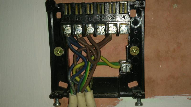
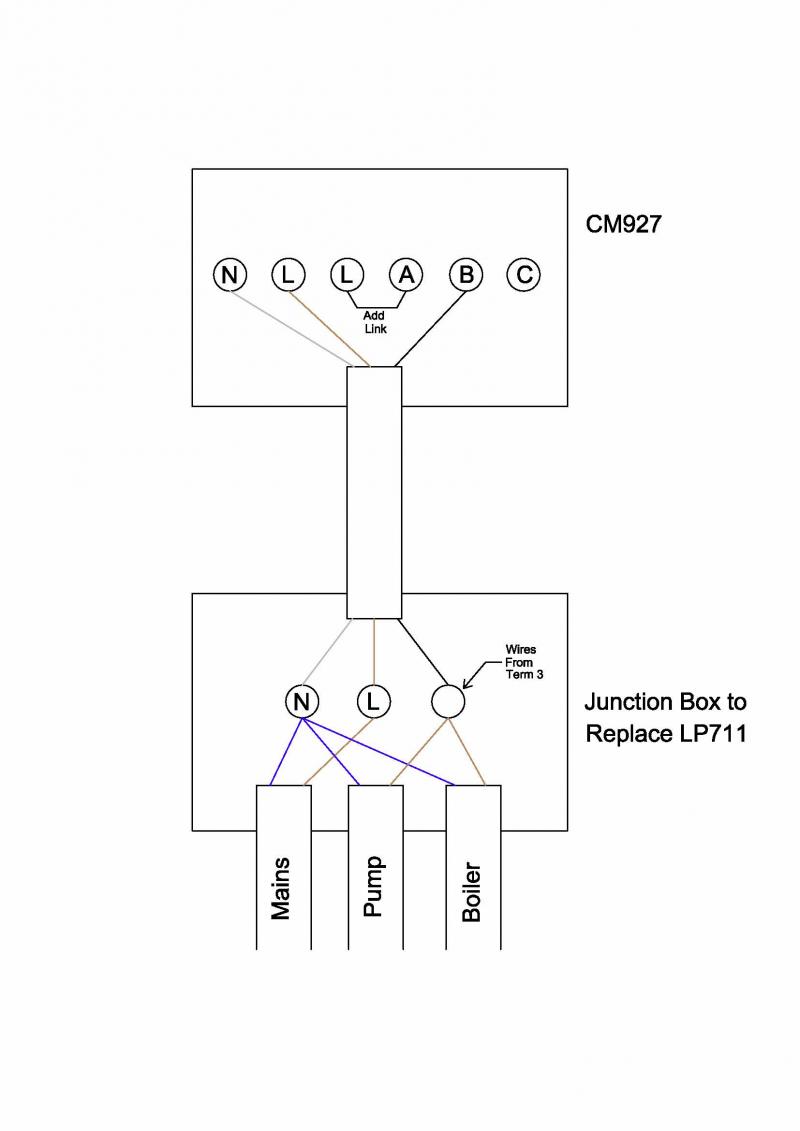
I wish to replace my Lifestyle LP711 controller with a wireless control CM927. Before I embark on anything I noticed that the boiler and pump are both wired separately into the LP711 (boiler and pump are separate). Can this be done and what wiring diagram would I follow (or can anyone send me a basic diagram). The boiler is an Ideal Classic and the pump is a Myson Compact. The boiler & pump are for Central Heating only.
Thanks in advance
Philip
 
Sponsored Links
Hello Agent007 and welcome to the forum. Can you explain what you mean by the following please?
The boiler & pump are for Central Heating only.
Do you not use the boiler for hot water?

You don't mention the type of system you have, i.e.
Gravity hot water and pumped central heating
Y Plan (3 port motorised valve)
S Plan (2 port motorised valves) etc.,

Also can you upload a photo or drawing of the existing wiring showing how it is connected at the LP711 terminals would be really helpful so as to know what wires are terminated there. (This can vary slightly from installation to installation)
 
Hi Stem, thanks for the reply. I’m going to show my ignorance now by saying I’m sure if its Y or S plan. The system consists of the small red pressure tank that is connected to mains water (it has a stop tap on and is only topped up when the pressure is low), the pressure tank feeds the boiler which then feeds the radiators.

The boiler is for the central heating only, not for the hot water supply.

Looking inside the LP711 it looks like the live wire for the pump and boiler are wired together in terminal 3.

If it can be done, would there be any reason why I couldn’t join the pump and boiler in a junction box and have a single cable to the receiver. I would have to install the receiver somewhere different to were the LP711 is for signal reasons
 
Sponsored Links
Perfect. thanks. Ignore the bit about "S" and "Y" plan they don't normally apply if you don't have hot water anyway.

Move the wires as follows.

Remove the link between "L" & "1" on the LP711 and install it between adjacent terminals "L" & "A" on the CM 927

The wires in "N" on the LP711 = connect to "N" on the CM927

The remaining wire in "L" (now that the link has gone) on the LP711 is the live supply = connect to "L" on the CM927

The two wires in "3" (pump & boiler live) on the LP711 = Connect to "B" on the CM927 (you can combine them as you suggest)

Terminate the earths appropriately.

Job done.

The wiring indicates that there is not an existing room thermostat installed elsewhere, but if there is, that will need removing and a small additional wiring mod.
 
Thanks Stem. I hadn't thought about including the mains feed in the junction box and only having one cable to the receiver. I was going to have two cables to the receiver, the combined pump/boiler as one and the mains as the other. Your way is much more tidy.
Cheers
Philip
 
Quick update. Fitted the CM927 over the weekend as per the wiring diagram above and all working OK :D Many thanks Stem

Just one quick question. My old controller was a timer version so the pump was running continuous while the heating was on. With the CM927 the pump switches off and on along with the boiler, will this shorten the life of the pump?

Merry Christmas everyone :LOL:
 
My old controller was a timer version so the pump was running continuous while the heating was on. With the CM927 the pump switches off and on along with the boiler
Are you sure? Looking at your photo, There are three cables. One cable (in the middle) provides the supply and is connected to L & N. Then the two remaining cables which I'm assuming are one for the pump and one for boiler were connected to the same terminal (3) and would have been switched on and off together. This arrangement hasn't changed in my diagram for the new programmer, both now go to terminal B
 
Stem, your wiring dia was spot on.
When the old timer control switched on, the pump and boiler came on together. When the boiler got to max temp the flame went out, until it cooled down a bit then it would fire up again (this could happen two or three time in a 5 min period). But the pump kept going all the time circulating water to the rads.
With the new controller (CM927) the pump and boiler switch on and off together (at least once every 10 mins as it goes through it’s ‘cycle’ or when the room temp is reached). I was just wondering if it was doing any good to the pump as it’s now continually switching on and off a number of times a day instead of coming on and off twice a day like it did with the timer
 
Sorry. The two live wires in Terminal 3 from the timer are the live wire for the circulating pump and the live wire for the boiler. This was so that they both becam live on when the timer switched on
 

DIYnot Local

Staff member

If you need to find a tradesperson to get your job done, please try our local search below, or if you are doing it yourself you can find suppliers local to you.

Select the supplier or trade you require, enter your location to begin your search.


Are you a trade or supplier? You can create your listing free at DIYnot Local

 
Sponsored Links
Back
Top