Help with wireless thermostat wiring

Joined
19 Oct 2006
Messages
116
Reaction score
1
Country
United Kingdom
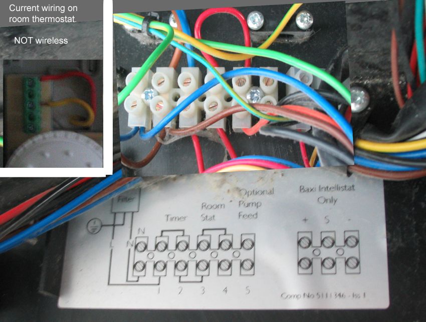
Current situation no timer but hardwired room thermostat.
Previously had a hard wired timer/thermo but elec fitted current thermo
only when the old one failed just to see me through the Summer.
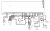
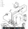
First image shows the boiler wiring and diagram.
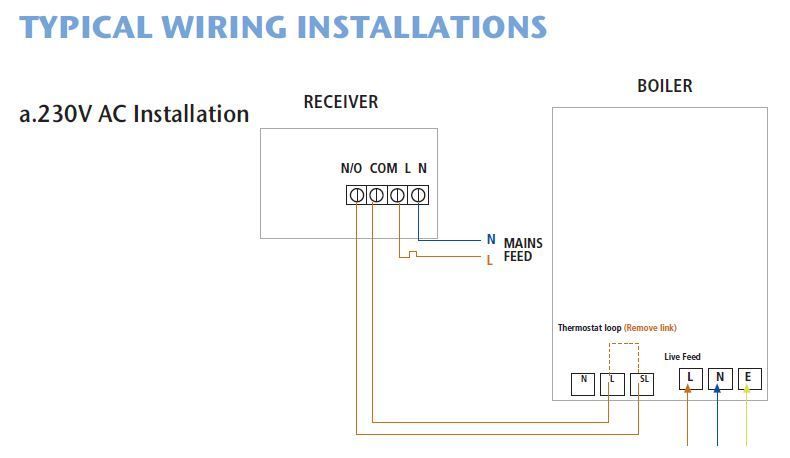
Second image the wiring diagram for wireless thermostat.

My understanding:
I take a live feed from the upper block terminals 1 & 2 that connects to
mains input for the boiler. (This wire comes from a fused spur on the
other side of the wall)
I then connect N/O & COM to the boiler upper block terminals 4 & 5.
I remove the red wire link in 4 & 5.


Sponsored Links
My understanding:
I take a live feed from the upper block terminals 1 & 2 that connects to
mains input for the boiler. (This wire comes from a fused spur on the
other side of the wall)
I then connect N/O & COM to the boiler upper block terminals 4 & 5.
I remove the red wire link in 4 & 5.
Not quite

numbers as per diagram.

At boiler
Where do the extra Browns and Blues from terminals N and 1 go?
 
Last edited:
From cable colours it would seem you have a motorised valve. If that's the case then the thermostat tells the valve to open then the valve tells boiler to switch on.
Central-heating.bmp
typical.
 
Apologies as I created my own numbering and never realised the label had numbers/letters on it.

The extra brown & blue go in to the PCB.
I havent opened up the PCB unit as yet.

I do have the PDF file for the boiler which gives the wiring diagrams. I could upload if required.
 
Last edited:
Sponsored Links
It appears Eric is correct.

Do you have a motorised valve and wiring centre somewhere.
What is the boiler make and model.
 
I cant see anything that states motorised valve in the manual. However when the original thermostat failed I seem to recall the plumber checking a valve that maybe sticking as I was getting hot water but no heating at the time, looking at that part on the boiler it states valve accuator.
It is a Baxi Combi 100HE

Wiring centre? Is that the main PCB?
 

Attachments

  • w1.JPG
    w1.JPG
    57.1 KB · Views: 237
  • w2.JPG
    w2.JPG
    81.5 KB · Views: 252
The valve(s) will be on the pipework somewhere and
a wiring centre is a separate row of terminal blocks nearby connecting the cables from all the parts - power, timer, thermostat, boiler etc.

Is this the right manual?
http://www.acwilgar.co.uk/pdf/system-100he.pdf
If so, see page 12.

I'm not sure why it states all that for a combi-boiler.
Do you have a hot water cylinder?
 
There is a actuator valve in an awkward spot connected to pipe work.
The wiring centre from your manual (page 12) coincides with the image in my first post.

That manual looks correct.

No hot water cylinder, hot water comes direct from the combi boiler.
 
There is a actuator valve in an awkward spot connected to pipe work.
Right.

The wiring centre from your manual (page 12) coincides with the image in my first post.
Yes, that is.
There is usually another nearby.
If the boiler one has been used for all the connections then you will have to work out from Eric's diagram where to connect the receiver.

Can we have a picture of the area around the connectors so that we can clearly see where all the wires go?


That manual looks correct.
No hot water cylinder, hot water comes direct from the combi boiler.
Ok.
 
Pictures, I can probably get better ones tomorrow if necessary.

Do you need them closer?

1 (1).JPG
1 (3).JPG
1 (4).JPG
1 (5).JPG
 
OK I will do it tomorrow as I may have to stitch some images together to get them larger and make sense, so will need time to edit them.
 
You used to have a hard-wired thermostat.

Now you have a wireless receiver hard-wired to the same wiring.

I fail to see why there is a problem.
 
No!, I had a hard wired programmable thermostat that failed. An electrician wired in a thermostat only (free) just to get by for the Summer. I now need the heating to come on whenever as we approach the colder months so need to install another programmer/ thermostat, but I want a wireless version.

The problem is I am not an electrician and appreciate any help I can get to make sure everything is safe.
 
Impossible trying to get an image that shows all the wiring and where it leads. I opened up the PCB as below.

mains.jpg
 

DIYnot Local

Staff member

If you need to find a tradesperson to get your job done, please try our local search below, or if you are doing it yourself you can find suppliers local to you.

Select the supplier or trade you require, enter your location to begin your search.


Are you a trade or supplier? You can create your listing free at DIYnot Local

 
Sponsored Links
Back
Top