

Hi,
My house has some lights on the outside which are wired in series and connected to a single switch inside the house by the front door.
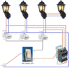
I would like to set these up so that when the switch is set to one position (L2) the lights simply all turn on, and when it is set to the other position (L1) the lights will be all off unless one of two PIR sensors are triggered. Either of the sensors will trigger all of the lights to come on.
I've found a couple of wiring diagrams online which appear to do what I want. I've attached both as Example_Circuit1.gif and Example_Circuit2.png
I've re-drawn this for the configuration that I think I need for my house and attached it as PIR_Sensor.png. The bit that I'm unsure on is the two neutral connections circled in red. The example diagrams that I found online suggest that these neutral connections are needed but I'm not sure what these are doing. They appear to be dead ends which serve no function
Can anyone explain what it is that I'm missing or what it is in my diagram that I've done wrong?
Thanks very much
My house has some lights on the outside which are wired in series and connected to a single switch inside the house by the front door.
I would like to set these up so that when the switch is set to one position (L2) the lights simply all turn on, and when it is set to the other position (L1) the lights will be all off unless one of two PIR sensors are triggered. Either of the sensors will trigger all of the lights to come on.
I've found a couple of wiring diagrams online which appear to do what I want. I've attached both as Example_Circuit1.gif and Example_Circuit2.png
I've re-drawn this for the configuration that I think I need for my house and attached it as PIR_Sensor.png. The bit that I'm unsure on is the two neutral connections circled in red. The example diagrams that I found online suggest that these neutral connections are needed but I'm not sure what these are doing. They appear to be dead ends which serve no function
Can anyone explain what it is that I'm missing or what it is in my diagram that I've done wrong?
Thanks very much
")