Bathroom Fan

Joined
27 Mar 2021
Messages
10
Reaction score
1
Country
United Kingdom
Hi,

first post so please bare with me.

just purchased some new bathroom fans to replace 15 year old fans in bathroom and ensuite.

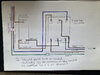
As it stands the existing fans are on off only with no timer and are switched from their own separate switch outside the bathroom. An isolator sits between the switch and the fan. Existing wire feeding fan is switched live, neutral and earth, with earth being parked and not in use in the fan.

the new fans are constant volume fans (Greenwood Unity CV3) and are to be running permanently. However they can be switched so they boost speed when you want and have an overrun timer before going back to constant volume setting.

problem is the new fans require a permanent live, but still the earth is not needed. It’s going to be very difficult to rewire new cable so my question is can I convert the earth cable to a permanent live cable in the circuit, all the way back to the switch, and through the isolator. Obviously I would cut back earth sheave and sheave in black for identification.

is this actually possible?

think I’ll get an electrician in to do the job but was curious as to whether this was actually allowable to make the job easier.

thanks,

Rich

since realised it’s not possible anyway as the earth isn’t sheaved through the cable. It’s bare. I’ll call an electrician.
 
Last edited:
Even if it was sheathed throughout the whole length it is not permissible.
Imagine someone wants to tap into that circuit via a junction box, for whatever reason, and they find what should be an earth wire and make a corresponding joint to it. They then find that when they turn something on, (assuming they have not tested before hand), the fuse/mcb keeps popping?
 
If you don't want to install new cables, extractors can be obtained that have a built in PIR motion detector, so that they run on trickle all the time and at full speed when people are detected.
Another option is to install a separate PIR next to the fan for the boost function.
 
Worked it out, but I need to fit a triple pole isolator. Do I go for 6A or a 10A isolator on a 6amp lighting circuit. Assuming 10A would be better?
 
The circuit has circuit breaker for 6A. The spec for the fan says max current is 2.1watts (=0.01 amp) Where will the 10amps come from?
 
Last edited:
the final fan in the utility, I cannot rewire, it’s impossible without lifting floorboards or taking down ceilings. So my question is, because the fan is a continuous running fan, which has a humidistat sensor, can I just put the switched live (L1) at the switch end into L2 and at fan end just put the live into the permanent live feed terminal? My thinking is that I just need the fan running 24/7 and this may be the way. Assuming if I did this the switch would effectively become redundant and wouldn’t do anything if it was switched?? There is a fuse adjacent to the switch would I need to rewire here also? Just want to make the existing switched live permanent, and trying to work out the best way to do it.

thanks in advance for any help.

PS. The power is coming from the lighting circuit, but the fan is operated (on/off) by its own switch and cabling. The fan is an older type fan with no overrun.
 
Last edited:
Having looked at the instructions.
https://greenwoodairvacblob.blob.core.windows.net/media-manager/9026?sv=2015-12-11&sr=b&sig=U7flIKGSh+mrI9zadY/J6vDQFn02PjseuomQwDIZ970=&se=2021-04-01T05:53:07Z&sp=r&rscd=attachment;filename=Unity CV3 Installation Instructions.pdf

I think that all you need to do is to wire the existing cable to L and N, and leave the switch on.
I think then that the fan then will run in trickle mode and boost when humidity goes up. Probably the humidity level is configurable from the control buttons and the app?

If you want to bypass the switch, move the wire from L1 to COM. Putting it in L2 will just make the switch work upside down. But I would leave it as it is, you’ll then be able to turn the fan off, if you need to.

thanks for that. Makes sense. However you’ve made me wonder whether I’ve actually wired up my switch and isolator to the other fans correctly now following your L2 comment. What I have done at the switch end is as follows:
Live feed comes in to Common at top of switch. Switched live at switch end goes into L1, this then goes to isolator where it connects into L1. Permanent Live feed at switch end goes into L2, this then goes to isolator to fan isolator
Having looked at the instructions.
https://greenwoodairvacblob.blob.core.windows.net/media-manager/9026?sv=2015-12-11&sr=b&sig=U7flIKGSh+mrI9zadY/J6vDQFn02PjseuomQwDIZ970=&se=2021-04-01T05:53:07Z&sp=r&rscd=attachment;filename=Unity CV3 Installation Instructions.pdf

I think that all you need to do is to wire the existing cable to L and N, and leave the switch on.
I think then that the fan then will run in trickle mode and boost when humidity goes up. Probably the humidity level is configurable from the control buttons and the app?

If you want to bypass the switch, move the wire from L1 to COM. Putting it in L2 will just make the switch work upside down. But I would leave it as it is, you’ll then be able to turn the fan off, if you need to.

Your comment about L2 above has made me rethink my wiring to the bathroom fans. These have all be run in with new 3 core and earth cable and a new 3 pole isolator. I have followed the instructions for wiring the fan and switch to the isolator, but I believe I may have the new permanent live feed in the wrong connector at switch end. At the switch I have live coming in which is connected to common. The switched live is in L1, and then I have connected the new permanent Live to L2. Should this new permanent live actually go to the common, with nothing in L2. I attach a coloured wiring diagram showing the cirruit wiring. Hopefully someone can advise if I have done it correctly. Thank you.
 

Attachments

  • wiring.jpg
    wiring.jpg
    283.7 KB · Views: 187
It depends what you are talking about.

On a two-way switch both L1 and L2 are switched lives, but

on the isolator L1,L1; L2,L2 and N,N are just the markings for the three conductors, each of which switches on and off whatever you connect to them.
 
It depends what you are talking about.

On a two-way switch both L1 and L2 are switched lives, but

on the isolator L1,L1; L2,L2 and N,N are just the markings for the three conductors, each of which switches on and off whatever you connect to them.

It is a one way switch. The fan is designed to be permanently on. The switch is used to boost the fan whilst having showers etc. Once finished you turn off the switch, and after an overrun period, the fan reverts to trickle.
 

If you need to find a tradesperson to get your job done, please try our local search below, or if you are doing it yourself you can find suppliers local to you.

Select the supplier or trade you require, enter your location to begin your search.


Are you a trade or supplier? You can create your listing free at DIYnot Local

 
Back
Top