• Looking for a smarter way to manage your heating this winter? We’ve been testing the new Aqara Radiator Thermostat W600 to see how quiet, accurate and easy it is to use around the home. Click here read our review.

Garage CU with Energy Meter

Joined
29 Feb 2024
Messages
30
Reaction score
0
Country
United Kingdom
Hi Everyone

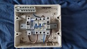
I've inherited a Mini CU in the garage extension and want to restore power there after decorating. It's fed from a 40A MCB at the Main house CU along a 6mm2 cable.

I'm wondering what your thoughts are on it. The feed supplies the box via a 32A MCB. I'm thinking that should be changed to a 32A or 40A RCBO.

The energy meter I have is rated at 45A (Eastron SDM120D). The terminals are set back a bit so I'm thinking I will need to use some 6 or 10mm to connect to the next MCB which then has the busbar.

See pic.
 
. I'm thinking that should be changed to a 32A or 40A RCBO
Is the 40a feed from the house RCD protected? If so as an RCBO is not necessary.
Looking again, the double unit in the middle is A 25amp RCBO. Is that supposed to be the main switch? How do you plan to configure the unit.

PS are you in Australia??:LOL:
 
Whoops don't know how the pic ended up inverted. Fixed it.

If I can use this box I will guys, all seems ok in it, just not very clean.

The 40A shares a busbar with a 40A RCBO which feeds the electric shower.

Re config I was going to install (from left) 40A RCBO - 45A Energy Meter - B20 - B10. Or, if possible (££) B32 - Energy Meter - 25A RCBO - B20 - B10. I don't think a 25A RCBO could be used as the main switch?
 
Last edited:
I googled and got 1745824268610.pngif this is what you are talking about? Then it will not need heavy cables, and technically should not be in the consumer unit. Only items approved by the manufacturer can be put in a consumer unit, as they need to have been part of the type testing.

I know we do put items like doorbell transformers in the consumer unit, but technically it is then a distribution board, not a consumer unit.

I see no picture, the top pair
1745824705118.png
of wires give power to the meter, the bottom pair
1745824770791.png
go to the CT coil, i.e. this 1745824832474.pngit says configurable, but I have not read the instructions as to how this is done. Maybe when the picture returns all will be made clear?
 
I have a few energy meters, three plug in, and a load of CT coils to monitor the solar. I see today my peak draw from grid, was 602 watts, at 04:44 am, which seems a bit high, but not really anything I can do about it, not a clue why that high, maybe all 4 freezers were running together, but even that seems not enough, and at that time, seems unlikely dishwasher was on.

But the two which one can be sure reasonably accurate, the smart meter and the export meter, are sealed units, I could not disable them, with a din rail mounted unit, it needs a supply to run, cut the supply to the meter, and one can still use power, but it would not register.

So of interest only, same as my solar inverter, it allows me to see import, export, consumption, etc. But likely not that accurate, so only of interest, it could not be used for billing.
 
Picture gone but my advice in post # 2 stands

Why the energy meter?
Apologies, not sure why the pic didn't upload. Tried rotating it and reuploading. Here it is.

@ericmark so would it need a dedicated box in which it has been type-tested... i'm guessing that might be a lot of hassle...

Energy meter is so I can see what's being used in that space, and also if I decide to make it habitable

I think it's probably wise to install a 32A or 40A RCBO to receive the feed from the main CU and go from there. No need for the 25A RCBO, it's too small. The energy meter I may have to forget about for now, would you have any suggestions for appropriate energy meters for this unit? It's Garo I think, need to check.
 

Attachments

  • 20250427_190107.jpg
    20250427_190107.jpg
    291.7 KB · Views: 55
That is not a consumer unit, it seems like an adaptable box being used as a distribution unit. The meter is not the one I found, so does not need a CT coil, but it clearly does not line up with the other units.

Having now seen the picture, I would agree with @Murdochcat and would get a proper consumer unit.
 
. No need for the 25A RCBO, it's too small.
But but but. You MUST have a double pole MAIN SWITCH. The only thing that qualifies for that purpose is the 25A RCBO.
As above, by the time you’ve added what you need, it’ll be easier cheaper to buy a new until. Don’t even know if you can get Shrack stuff anymore.

PS The 20A MCB at the right is broken and needs throwing away.
 
I can advise that meter will clip directly into one of these https://www.screwfix.com/p/british-...le-2-way-populated-garage-consumer-unit/453vf and line up with the MCBs and it comes with a 40A RCD for £33.
As has been mentioned it will not line up with the busbar, In my situation it didn't matter as only required to monitor the 32A MCB so wired between MCB and load.
As also mentioned your pic shows it not lining up with the existing MCBs but to my mind it looks like it is not sitting flat on the DIN rail.
 
I think it's probably wise to install a 32A or 40A RCBO to receive the feed from the main CU and go from there.
The energy meter may be working, and it could be used in a new consumer unit.
The rest of the devices and the enclosure are scrap. They cannot be used for anything.

As for the rest:
What type of cable is used between the house consumer unit and the extension, and how is it installed (such as underground, fixed to a wall or whatever) and how long is it?.
What is it protected by - just a MCB, or an MCB and RCD, or something else? Add photos if unsure.
 
I just went ahead and got the RCBO and gave it a go. I have a new found respect for the time and effort sparkies put in to these installs, notwithstanding the fact I was only doing a Mini! It's really tough to manage each wire and get them lined up clearly. I ended up just keeping the neutrals, earths, and lives together using a cable tie. I made sure to place them in the right numbers on the neutral and earth bars according to placement.
So I bought a 40A RCBO which is mounted from the right, so I changed the configuration. (From right) 40A RCBO - 45A Energy meter - 32A MCB (not being used, put it there for future) - 20A MCB (needs to be replaced when I get a chance, got distracted and didn't buy it when getting the RCBO!) - 10A MCB.
I wired the Energy meter in 6mm2. The incoming feed from the 40A MCB in the Main CU is 6mm2. There's a separate 10mm2 earth coming from the Main CU and another going to the Earth rod outside. The extension Mini CU site is roughly 8-10 meters from the Main CU, cabling is though the joist spaces. The 40A MCB on the Main CU is on the lower rail (dual split) - protected by the Main switch? There's an RCBO for the electric shower beside it. Or could it need a dedicated RCD after the Main switch? Job for a qualified sparkie.
They all fit nicely on the DIN Rail, but the 10A Shrack is a little bit shorter than the rest so I had to bend the bus bar slightly to make it fit. The busbar terminals at the energy meter do not touch it, I erred on the side of caution and broke them in half, and then placed some sheathing over the halves (they were blocking the energy meter test points). I ran out of earth sheathing so had to use some of the larger sheathing on a 2.5mm2 earth.
I realise it's not the tastiest work you'll ever see but it's all solid and safe. But, unfortunately, the energy meter is not tracking usage. I hooked up the light and a socket temporarily and boiled the kettle a few times. It's still at zero. The instructions are a little confusing - it doesn't make clear whether the little terminals on the front are for testing only. I don't think it makes sense that they should be connected - but I find with electrics there's always a way to make it make sense!!
Thanks guys for your patience with me.
 

Attachments

  • 20250428_194700.jpg
    20250428_194700.jpg
    234.7 KB · Views: 46
  • 20250428_194504.jpg
    20250428_194504.jpg
    297.5 KB · Views: 55
  • 20250428_191220.jpg
    20250428_191220.jpg
    174.5 KB · Views: 46
Can you take a pic from below to see what's terminated where, it doesn't look right to me
 

If you need to find a tradesperson to get your job done, please try our local search below, or if you are doing it yourself you can find suppliers local to you.

Select the supplier or trade you require, enter your location to begin your search.


Are you a trade or supplier? You can create your listing free at DIYnot Local

 
Back
Top