I thought I'd share my central heating design in case anyone finds it is useful. I should add I'm not just blowing my own trumpet here, when the boiler manufacturer's engineer saw the setup he was impressed so much that he shared it with a colleague too.
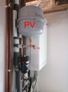
Picture Key:
B: Gas Boiler (condensing, system boiler)
F: CH Feed tap
G: Gas tap
R: CH return tap
FL1: Fill Loop 1
FL2: Fill Loop 2
CD: Condensate Drain
PV: Pressure (expansion) Vessel
MF: Magnetite Filter
PVI: Pressure Vessel Isolator (service valve)
PVD: Pressure Vessel Drain
Gas boiler (B), isolation taps (F, G, R), Fill loop (FL1), Pressure Vessel (PV) and Magnetite Filter (MF) are pretty standard stuff. PV is on return side so that boiler pump (internal to boiler) increases the pressure so no chance of negative pressure to suck in air (e.g. if PV was on feed side it would be PV - pump head on return side and if this was negative then air could be sucked in, promoting corrosion). Likewise MF is on the return side to remove magnetite before it gets to the pump. And FL1, the normal fill loop is on the return side so the flow is going to be through the pump in the normal dirrection when filling.
The purpose of PVI and PVD is twofold. Firstly, in the event that the PV fails and needs to be replace you can isolate it and just drain off a small amount of water rather than the entire system. Secondly, in order to check the static air pressure in PV you need to drop the CH system side pressure, otherwise you are just measuring the CH pressure. Again using the isolation valve and drain reduces the water you have to lose.
For example, my PV is 12 l, the static pressure is 1 bar, my CH/HW system is ~100 l. I set my cold pressure to 1.2 bar hence my PV air volume is now 10 l (12x1/1.2). When the CH is hot the water expands by a maximum of 4%, e.g. 4 l in my case so air in PV is now 6 l and pressure is 2 bar (12x1/6) which is well within the 3 bar limit for the boiler, the point where pressure relief valve operates.
CD is perhaps a bit unusual. My gas fitter persuaded me to change from having the CD going into a second trap, which is how I originally had it, into a direct connection to the inside sewer. CD is after the the boiler trap of course. The maker's installation instructions allow either type of connection. The benefit of 2 traps is that if the sewer backs up then this floods into the house not inside the boiler. I don't think in my case that is a serious risk, the boiler is high up and there are plenty of lower traps to let any sewage escape should the sewers ever back up to that extent. The benefit of direcly connecting CD is that if the boiler trap dries out or gases leak through the boiler trap (very strong wind directly onto flue perhaps) then the poisonous flue gases doesn't escape into the house but go into the sewer. That seems the higher risk to me which is why the gas fitter persuaded me to redo it.
FL2 functions with FL1 as follows. British standards allow a mains water pressure cold flush of new installations. That's cheaper than paying for power flushing. Hence I isolate the boiler with F and R, then I connect a drain pipe to FL2 and use the filling loop FL1 to drive mains pressure water backwards through the radiators and out of FL2. Of course only one radiator is turned on at a time during the flush so each gets a the full force of the flush. Then by swapping the filling loop to FL2 and the drain pipe to FL1 I can flush in the normal direction. And I can flush the boiler by conecting the filling loop to FL1, the drain to FL2 and turning on F and R. I don't think it would be a good idea to reverse flush the boiler although you could do that too with FL1/FL2. And of course any time in the future the system needs a flush this is easily done with no need for the cost of a power flush.
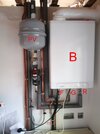