Vent-Axia ACM100T 17104020F Circuit Board

Joined
9 Oct 2025
Messages
7
Reaction score
1
Location
London
Country
United Kingdom
Hi everyone,

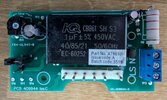
I'm a beginner trying to repair a faulty fan control board (PCB Part No: 409944) and would appreciate some advice before I attempt a repair. I've tried searching for a direct replacement board but haven't been able to find one for sale, so a component-level repair seems like my only option.

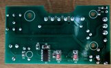
The board is dead. When I inspected it, I noticed a faint smell of burning and some very slight, dark discoloration on the back of the PCB, right where the main resistor (R6) is located.

I am new to using a multimeter, so these are my best-effort readings taken while the components were still on the board, I've read that the readings from the capactiors while still attached the board is not reliable:

Resistor: Reads ~22kΩ.
Capacitor: Reads ~0.35µF.
Capacitor : Reads ~10.12µF

Given the burn smell and discoloration near the resistor, combined with my readings, does it sound like I'm on the right track? My plan is to replace the 10kΩ resistor.

Does this sound like a correct diagnosis to you all? Is there anything else I should be checking before I order parts?

Thanks for your help!
 

Attachments

  • original_b91d3f7f-8511-41e3-9a10-5881d7406a38_PXL_20251009_221222198.NIGHT.jpg
    original_b91d3f7f-8511-41e3-9a10-5881d7406a38_PXL_20251009_221222198.NIGHT.jpg
    208.8 KB · Views: 49
  • PXL_20251009_221210356.NIGHT.jpg
    PXL_20251009_221210356.NIGHT.jpg
    169.7 KB · Views: 37
What do you mean by the board is dead?
I may be wrong but doubt it is a resistor that has failed. One of the capacitors is much more likely. you can't get an accurate reading measuring of components in circuit.
Have you tried changing the jumper to a different position to see if it works at other speeds

1760070049539.png
 
The resistors do heat up. You can't test components when they are still in the circuit board. other circuit items will make any measurements wrong.
Quite honestly, you can get new replacement timer boards from Amazon/FleaBay etc for about a tenner...
 
Last edited:
Resistor : I can't quite make out if the third band is red or orange. If red then the value is wrong but I suspect it is orange
Capacitors : need to be out of circiuit to be sure. You can do fancy things to measure in-circuit but not worth the trouble - easier to reove a leg. What are the values on the side of C1 and C2?
 
The resistors do heat up. You can't test components when they are still in the circuit board. other circuit items will make any measurements wrong.
Quite honestly, you can get new replacement timer boards from Amazon/FleaBay etc for about a tenner...
The board on the link don't seem to be compatible, don't have the pin connectors and don't look the eright size to fit the housing
 
@jj4091 the motor is trying to start but can't, so it makes a very faint noise. I've tried all 3 speed settings, no change
 
I wonder if a polyphase fan motor? It is today quite common to turn AC into DC, store it in a capacitor, then turn it into 3 phase AC to run a motor. Even the little fans in a computer did that. In which case, your chances of repairing it using a soldering iron and multi-meter are next to non.
 
I have the same extractor fan in the other bathroom, switched the PCB and motor works. So it's got to be the PCB
 
Again just a guess, but I would think it is probably the IC on the back of the board that has failed. Capacitors usually become bloated when they fail so physically check that first, You have established that it is the board that is faulty and cannot locate one, so contact Vent Axia and ask them to supply one. I believe, though might be wrong, that they are legally obliged to supply spare parts.
 
As above, electrolytic capacitors usually have obvious signs of failure, either swelling, or leakage, and resistor would show indications of burning - Both look fine in the photos, so probably OK. Which leaves just the controlling IC on the back of the PCB. The chances of identifying the IC, and being able to replace it, even with the correct equipment, without lots of experience - almost nil.
 
The large 22K resistor will get warm (by design). It probably won’t have failed itself, but it may have damaged the PCB (though I don’t see any obvious problems in your photo - I’d look under a good magnifier or microscope) or it may have cooked other components, most likely the adjacent capacitor. If I were you, I’d try replacing that capacitor - but only because I have a replacement handy. Failing that I’d look at voltages elsewhere - but this is problematic because it is all live and therefore dangerous, unless you have some sort of isolated mains supply.
 
If I were you, I’d try replacing that capacitor - but only because I have a replacement handy. Failing that I’d look at voltages elsewhere - but this is problematic because it is all live and therefore dangerous, unless you have some sort of isolated mains supply.
I am new to using a multimeter, so these are my best-effort readings taken while the components were still on the board, I've read that the readings from the capactiors while still attached the board is not reliable:

Seems very unlikely, and potentially deadly advice, to suggest live testing, if the OP is not even familiar with the use of a multimeter!
 
I've phoned Vent-axia for a spare part, they didn't have one in stock and promised to get back to me next monday with an update
 
Seems very unlikely, and potentially deadly advice, to suggest live testing, if the OP is not even familiar with the use of a multimeter!

I didn’t suggest live testing! I specifically said that it would be dangerous without some sort of isolated supply.
 

If you need to find a tradesperson to get your job done, please try our local search below, or if you are doing it yourself you can find suppliers local to you.

Select the supplier or trade you require, enter your location to begin your search.


Are you a trade or supplier? You can create your listing free at DIYnot Local

 
Back
Top