110volt transformers with centre tap 55volts???? confused?

Joined
10 Dec 2008
Messages
135
Reaction score
0
Location
Caithness
Country
United Kingdom
hello everyone!!

im getting confused as too what this means,ive been hearing about this 110volts transformers and that there is something to do with a centre tap and 55volts is that right could somebody please explain what is meant by this and do you have to take live,neutral and earth supply into a 110volt transformer, and take two lives out from it or something really confused what it all means

any help would be appreciated or any good websites with info on this topic!!


cheers
 
Sponsored Links
It basically means what it says, the centre of the secondary winding is tapped to earth. As the secondary output is 110V, the voltage between any side of the winding (there is no Line or Neutral) and earth is 55V so reducing the shock severity as there would be with 110V (depending on conditions as well!!)
The transfomer is still fed with L, N and E (for a 230V input)
 
so when you say secondary windings does that mean the out going part of the transformer ye?

is there any good websites showing how this looks or at?
 
Sponsored Links
Under UK rules 411.8.1.2 the maximum voltage allowed with reduced low voltage is 63.5 volt this allows one to use a three phase transformer using school boy maths Sin(120 degrees) = 0.866025 x 63.5 = 54.99261 so two phases on a 3 phase supply gives 110 volts between phases the same as two phases on a split phase supply.
You do not really need to understand that bit it just explains why the limit is 63.5 volt rather than 55 volt to earth.
The idea of course is safety but it does require a lot more control as every switch needs to be twin pole and using fuses can give the user a false indication of no power when really power is still there.
Some of the yellow step down transformers are really dangerous, as instead of fusing the output they fuse the input. Also they sometimes have two 16A outlets protected by a single fuse so a 3KVA transformer may be protected by a single 13A fuse. This means that 27 amp can be drawn at 110 volt or 54 amp at 55 volt.
On building sites it is common to have lead plugged into lead and I have found 5 x 25 meter leads plugged into each other.
At 1.5mm² a 25 meter lead has a resistance of around 0.725 ohms which means with a short circuit 76 amps will flow and a 13 amp fuse on the supply cable will blow. However with two leads that drops to 38 amp so the fuse will not blow but the cable will get very hot especially if in is touching itself anywhere.
The smaller 1.5KVA transformers with 7 amp fuse or trip in incoming 230 volt supply are not so much a problem although the maximum without blowing fuse is 30 amp at 55 volts. Also the chances of the short circuit being bang on the point where 30 amp will flow is slim in fact most have a 6 amp thermal trip so only 25 amp.
As a result many firms only use the 1.5KVA transformers which are also lighter or the much larger fixed transformers where the output is protected.
Site fires are normally started either shorted 110 volt cables or 300W halogen lighting.
The BS7671:2008 allows 5 seconds to disconnect the supply (411.8.3) should there be an earth fault and with small hand held transformers the impedance of the secondary winding means the only way this can be achieved is with a RCD device. Only 5KVA and above transformers have a low enough impedance to be able to use a MCB.
However although we saw a big drive to sell 17th Edition consumer units to date I have not seen a single hand held yellow transformer with a RCD built in.
I have seen in line RCD’s for 110 volt use and because they have to work at less than 55 volt they all seem to be the active type.
This has also caused problems with generators as to reduce fuel consumption many now have a current sensing device which allows the generator to tick over when not being used and only speeds up to 3000 revs when load is applied. This means one has to plug in a halogen lamp to keep them revving so the RCD to magnet mount drill does not drop out. So when bulb blows drill falls off?
As a result I would say there needs to be a big re-think on use of 110 volt.
Guess who use to work in construction?
 
Very good Eric :D
Now tell us why the fault voltage (indirect contact touch voltage) does not exceed 40 volts for any winding arrangement, single or three phase? You will need superposition theorem and lots of spare time :D.

Also tell us why BS 7375 does not insist on any particular disconnection time, but BS 7671 does - funny that because the first sentence in BS 7671 Section 704 is "This section should be read in conjunction with BS 7375."

BTW - have you given the use of RCDs built into site transformers proper consideration?
Why would you need them in an inherently safe (from a shock protection point of few) system such as an RLVS. After all, they would most likely break after the transformer has been kicked or dropped a a couple of times :D
 
Fault voltage Uf is the voltage, which will be found on exposed conductive parts. During a fault so if we look at a house for an example on a TT system without a earth leakage trip with 13 amp flowing to earth rod with a resistance of 10 ohms the soil pipe could have a voltage of 130 volt to true earth, hence why we must use a RCD on a TT system.

In real terms there will also be a resistance in the supply cable so it would be lower but since the 10 ohm of earth rod is only a figure taken as an example the whole calculation is not real.

If the fault was from a 110 volt transformer i.e. a phase is connected to earthed gas water pipe which is bonded to the earth rod then the voltage will be 55 volt divided by sum of system impedance and earth rod times by resistance of earth rod. So if the impedance from the transformer is 2 ohm and the earth rod is 10 ohm then the fault voltage would be 45.8 volts. If the earth rod was 20 ohm then you would get 50 volt and since an earth rod where a RCD is used can be up to 200 ohm you could get 54.5 volts. Because the 110 volt transformer isolates incoming supply from out going supply the fault would not trip any RCD on the supply which the exception of the old voltage operated type.

Normally of course water, gas, and soil pipes add to the earth rod earth and we do get lower figures in a house even on TT system.

However using a 110 volt transformer in a house does increase the danger of getting a shock rather than decrease it as intended but a house is not a construction site or farm so it is not required.
So since I have failed to show how it is below 40 volts I will pass it to “NotHimAgain” to show the maths involved.

As to Section 704 I did not quote from this section I gave 411.8.3 as my reference so the 5 second disconnection time is not anything to do with BS 7375.

If you have a transformer with a low enough ELI then you would not need a RCD. Although the large 7.5Kva transformers found on construction sites may not require a RCD when drill etc designed to be used on construction sites are used else where using a small portable transformer there is a problem.

Construction sites don’t have 230 volt 13 amp outlets, so these small transformers are not used, only where alterations to existing buildings are being done do you get 13A sockets available to plug these small unit in.

As to the argument it may break so we will not use it not really a good excuse. The RCD’s built into leads seem to stand all the knocks and bumps of a building site covered in their rubber outer layer so I am sure a RCD can be combined into a 110 volt transformer at design stage with adequate protection.

As an add on I would agree not really an option to add to existing case. However to change the outlet sockets to some unique type and have a small lead with unique plug RCD and standard 16A socket would work.

Years ago when building Sizewell Power station nuclear electric did have RCD’s on their 110 volt transformers and John Laing as it was then got into trouble as some of their transformers had a single 20amp MCB to protect two 16A socket and they had to remove those transformers from site. This caused a further problem in that the vacuum cleaners had 3 motors and took more than 16 amp and had to be converted to 32A or 3 phase and yes we had 3 phase 110 volt on site I think only site I can recall with 3 phase 110 volt used. A 4 core 1.5 or 2.5 mm cable is smaller than a 4 mm 3 core cable so yes there is a point in using 3 phase. It also meant the splitters plugged into the 3 phase and than had 3 single phase outlets so splitters could not be plugged into splitters.

Plus of course people worry about their 110 volt transformer going missing. How many times have you seen the long 230 volt extension lead feeding the 110 volt transformer? In view of what is being discussed not sure if that method is not safer too?
 
I don't understand your fault path with a transformer plugged into a TT system, surely the fault path will be back to the 110v transformer secondary? The installation earthing/bonding will provide a path for the current to flow back to the secondary, the electrode holding the lot at or about earth potential?
 
When we assess fault characteristics for an RLVS, or a normal installation, we are generally concerned with faults between the line conductor (R1) and an exposed-conductive-part. This exposed-conductive-part is usually connected to the main earth terminal via a circuit protective conductor (R2).

Faults (zero impedance) between line conductors and extraneous-conductive-parts, such as your gas pipe, are far less likely, and are not generally considered. They could be, but we would need to know the impedance of the extraneous-conductive-part between the point of fault and the point of any connection to the main earth terminal. Extraneous-conductive-parts are therefore not generally included in the earth fault loop path.

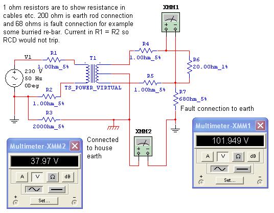
So when you assess the touch voltage (Ut) for an RLVS you are concerned with the impedance of the transformer winding, the impedance of the line conductors and the impedance of the circuit protective conductor. The transformer earth reference electrode is not included in the fault current path. It does, however, provide the earth reference, and would provide a path for the touch current (It). This is the body current that actually gives the shock - see BS EN 60990:2000.

So as I said in my last post - you need superposition theorem and about ten pages of circuit analysis :D.

The principle is to consider the transformer secondary as two 55 volt circuits consisting of a line conductor and a circuit protective conductor (cpc). Various faults are applied both near the transformer and far from it (i.e. at the end of a final circuit). This is done for each 55 volt circuit and the results are superimposed to complete the analysis - its too complex to describe in detail, but the general idea is straightforward. This is also carried out for the three phase version.

Check out HSE guidance on the 110 volt system - somewhere in that you will see the 40 volt figure mentioned, and Paul Cook correctly quotes 30 volts on page 84 of his Commentary.

Ericmark said
As to Section 704 I did not quote from this section I gave 411.8.3 as my reference so the 5 second disconnection time is not anything to do with BS 7375.

Its all part of BS 7671. The point here is that the standards adopt different approaches and actually end up in disagreement.

BS 7671 follows the traditional route of specifying a 5 second disconnection time, but this ignores the fact that Ut is less than 50 volts, and therefore, disconnection in any specified time is not essential for shock protection.

So why make a fuss - well if you insist on a disconnection time you end up imposing an impedance limit on the circuit. That is, the impedance must be low enough to operate an overcurrent protective device. The usual alternative would be to use an RCD but let's leave that option at the moment.

A limit on impedance imposes a limit on circuit length and, from memory, you end up restricting the length of a 1.5mm² extension lead to around 16 metres. Now, as Eric has pointed out, leads get plugged into leads and any limits are ignored :D.

RCDs - IMO they are just not robust enough to be housed in a portable transformer for use on site. In
addition they add nothing to a system that, from the shock protection point of view, is inherently safe.
 
Had now more time to look.
I still want to know more about the “superposition theorem” is it anything similar to Thévenin’s or Norton’s theorems? I seem to remember that one of them ended up with reams of paper work and all too easy to make one mistake.
I realise now after laying out the circuit in electronics workbench that what I was seeing in my mind’s eye was wrong.
Here is the scenario I was seeing with the results given by electronic workbench which when compared with results using Thévenin theorem in the past was quite close.
I will be first to admit in real terms unlikely to do one any permanent damage but although I can see the safety features in using split phase 110 volt on a real construction sites. However where it is used in premises where 230v from RCD protected 13 amp sockets is available I think it introduces as many dangers as it removes and in real terms it’s only advantage is one can use the same tools in both environments.
And I have not included the trip hazards of having normally a single transformer with multi trailing leads.
 

DIYnot Local

Staff member

If you need to find a tradesperson to get your job done, please try our local search below, or if you are doing it yourself you can find suppliers local to you.

Select the supplier or trade you require, enter your location to begin your search.


Are you a trade or supplier? You can create your listing free at DIYnot Local

 
Sponsored Links
Back
Top