250V / 500V IR differences

Your results are interesting and for such a huge difference between the two one can rule out capacitance one would think. However having said that my battery meter I always do a short reading to conserve the batteries but with the PAT tester mine a very old Robin has a meter not a digital display and I have noted a few times a low reading which seems to stay that way for a few seconds and then the needle starts to drop quite quickly.
[I presume you're talking about a needle indicating current - such that 'needle dropping' corresponds to increasing resistance]
I get the impression that my Fluke makes an attempt to avoid this problem. Although the instructions say that one should hold the button down until "the reading settles and the tester beeps", in reality there is no displayed reading until the tester beeps, and it often takes 2-3 seconds (sometimes more) before it bleeps. I therefore get the impression that the tester is actually looking at the 'settling' reading and not displaying it (and bleeping) until it decides that the measurement has more-or-less 'settled'. I'll try to do some experiments (not easy), since the manual is not very helpful in this regard. Does anyone know whether there is some sort of 'technical manual' in addition to the usual 'user manual'?
What I wonder is if that point where reading starts to drop will be reached quicker with 250 volt reading as the inverter in the meter must have a limited output.
Possibly. However, I'm not sure what the mechanism of this 'dropping' (again, I presume you mean increasing resistance indication) - capacitance is the only obvious candidate, and, as you say, that surely could not explain the magnitude of what I have observed? In any event, at first sight this didn't ought to be voltage-dependent, since the shape of the capacitive discharge curves should be the same (just shifted in magnitude), regardless of voltage.
Until you re-test holding the button will will not know of course.
Indeed so - although, as I have said, although I haven't been doing so deliberately, I'm pretty sure that I usually do, by habit, hold the button down for quite a while after the tester has beeped and displayed a reading. In the meantime, I've got quite a long run of SWA in my garden here, so might experiment to see how my meter behaves with it.

Kind Regards, John
 
Sponsored Links
Leaky insulation can be caused by many different things. Dampness, chemical breaking down of the insulation material. carbon deposits from scorched cable.....and several others. ... Some of these will have a resistance that is voltage dependent. For example dampness leads to corrosion which can produce metal to metal oxide junctions which have a semi-conductor effect which has a break down voltage. The junction will appear as a perfect insulator when tested below the breakdown voltage and a low impedance ( poor insulation ) when the test voltage is higher than the break down voltage.
All true. However, if you recall, when I recently undertook my experiments, it seemed that these (e.g. electrochemical and breakdown) effects were only resulting in erroneously high IR readings with very low test voltages (e.g. multimeters) and that IR readings seemed independent of voltage (unless/until one actually broke down the insulation!) provided that the test voltage was above about 30V.

Kind Regards, John
 
What I wonder is if that point where reading starts to drop will be reached quicker with 250 volt reading as the inverter in the meter must have a limited output.
Possibly. However, I'm not sure what the mechanism of this 'dropping' (again, I presume you mean increasing resistance indication) - capacitance is the only obvious candidate, and, as you say, that surely could not explain the magnitude of what I have observed?
I've just realised that I got a bit confused by what you wrote, which leads me to wonder what you did actually mean by 'dropping'. As explained, whenever I tested at 250V I consistently got ">200 MΩ" results, so the only sort of settling/dropping I could have seen would be a reduction in IR to below 200 MΩ - and, I have to say, I would find it even more difficult to think of a mechanism for a 'settling' in that direction. Maybe you meant to suggest was that 'settling' (increase in indicated IR) might take longer at 500V (or 1000V) - whilst that would perhaps make more sense in terms of either capacitive or thermal explanations, I really don't think that either of those issues could explain the differences I saw, even if I didn't observe the readings at 500V and 1000V for long enough.

Kind Regards, John
 
In the meantime, I've got quite a long run of SWA in my garden here, so might experiment to see how my meter behaves with it.
OK - experiment done. It's a run of about 50m of underground SWA, which has been there for a long time.

With 250V, 500V or 1000V, the IR is 'off scale' (>200MΩ, >500 MΩ or >1000 MΩ respectively) immediately a reading is first displayed, and remains unchanged no matter how long I hold down the test button. However, adding a shunt resistor whilst the button is still held down does change the displayed reading, confirming that the meter does, indeed, respond to changes whilst the button remains pressed.

With a 0.47 μF capacitor (far far more than one would ever get from a cable), it takes well under 2 seconds for the reading to 'settle' (rising) to a reading of >200 MΩ at 250V (the capacitor is not high enough rated for 500V or 1000V tests!),

Kind Regards, John
 
Sponsored Links
... Exactly. I didn't actually say this, but once I detected the anomoly, I repeatedly jumped backwards and forwards between 250V and 500V, with consistent results. Immediately after (seconds) I'd got a ~3 MΩ reading at 500V, I would get a >200 MΩ reading at 250V, and vice versa. ... It will be interesting to see if I still get similar results when I repeat the measurements, probably in a few days' time.
Update ...

I think I've discovered the cause of what I was experiencing, even if it remains a bit odd. Systematic testing and exploration of the circuit led to the discovery of a (previously unknown) dead (not tripping at all) RCD hidden at the back of a kitchen unit. Taking this out of circuit resulted in IR returning to the expected 'off scale' value (>500 MΩ) at 500V as well as at 250V (>200 MΩ).

I therefore can but presume that the electronics in the dead RCD were resulting in the ~3 MΩ readings I previously got at 500V - but it still seems a little odd that there was the repeatable difference at 250V and 500V. Something in the electronics presumably only became very slightly conductive at voltages above 250V, yet no permanent damage was done by the 500V testing, since I could always get a 200 MΩ reading by reverting to 250V testing. Of course, the fact that this RCD was 'dead' means that almost anything is possible!

Has anyone got any experience of (deliberately or unintentionally!) IR testing an RCD?

Kind Regards, John
 
, yet no permanent damage was done by the 500V testing,
Are you sure?, since....
discovery of a (previously unknown) dead (not tripping at all) RCD hidden at the back of a kitchen unit.
I was perhaps not clear enough in my wording. Yes, the 500V may have killed the RCD. However, what I meant was that the 500V did not do anything permanent, in terms of breaking down components, insulation etc., to result in the low-ish IR, since it would always be >200 MΩ if immediately tested again at 250V. In other words, whatever the ~167 μA was leaking through at 500V allowed less than ~1.25 μA (quite possibly virtually no current) to flow at 250V, reversibly and repeatedly.
Has anyone got any experience of (deliberately or unintentionally!) IR testing an RCD?
It seems you have... they don't work afterwards :LOL:
As above, possibly - but I was rather hoping for reports as to whether others had experience of 'IR testing RCDs', so that I could judge how likely it was that this was the explanation! I say 'possibly' because I think the RCD could easily have been dead before I did any IR testing (although I suppose it could have been killed by earlier IR testing). It certainly failed to trip (otherwise we would have been pulling out a lot of hair!) on several occasions (2-3 years ago) on which water in the shed caused the (known!) RCD at the CU to operate repeatedly - that could of course, have been 'chance', but it makes one wonder whether the 'unknown' RCD was functional even then.

Kind Regards, John
 
I think I've discovered the cause of what I was experiencing, even if it remains a bit odd. Systematic testing and exploration of the circuit led to the discovery of a (previously unknown) dead (not tripping at all) RCD hidden at the back of a kitchen unit. Taking this out of circuit resulted in IR returning to the expected 'off scale' value (>500 MΩ) at 500V as well as at 250V (>200 MΩ).

I therefore can but presume that the electronics in the dead RCD were resulting in the ~3 MΩ readings I previously got at 500V - but it still seems a little odd that there was the repeatable difference at 250V and 500V.
Not at all odd.
I have a couple of extension leads at home which were "scrapped" from work (many years ago) after failing PAT. They have surge protection (probably MOVs) which become conductive at the 500V the sparkies were using but are non-conductive at 250V. I did get the sparky to do a test on them at 250V and they were fine, but as "they use 500V for IR tests" then as far as work was concerned they failed. I offered to 'scrap' them for them.

So it's far from unlikely that the electronics have some surge protection (or similar) which becomes conductive at some voltage above around 350V, but is non-conductive at 250V.
 
I have meggered a ring main L-N with a TV plugged in and that survived... :LOL:
 
... Not at all odd. ... I have a couple of extension leads at home which were "scrapped" from work (many years ago) after failing PAT. They have surge protection (probably MOVs) which become conductive at the 500V the sparkies were using but are non-conductive at 250V. ... So it's far from unlikely that the electronics have some surge protection (or similar) which becomes conductive at some voltage above around 350V, but is non-conductive at 250V.
Fair enough - but, in context, I personally did find it rather odd - or, at least, surprising. You are talking about one of the very few electronic components which will (consistently and reversibly - and, in the case you mention, deliberately) be non-conductive at 250V but conductive at some voltage between 250V and 500V. However, I concede that it is possible that an RCD would contain a component deliberately with such functionality - so that is one possible explanation. Of course, in my case the RCD was 'dead', so it's quite possible that some component was not behaving normally, anyway.

Another possibility which occurred to me was a diode with a PIV between 250V and 500V (i.e. behaving as a very high voltage zener when reverse-biased from a 500V source). The test current might not have been enough to permanently damage the diode when tested at 500V (i.e. it really would just behave as a zener), hence making the phenomenon reversible (and 400V PIV diodes are widely used).

When I have time, I'm going to dissect the RCD in question and see if I can discover the explanation.

Kind Regards, John
 
When I have time, I'm going to dissect the RCD in question and see if I can discover the explanation.
Great, nothing quite like a ritual disemboweling :LOL:
I'll let you know if I discover anything useful.

In the meantime, even though hardly necessary (given the theory), I have confirmed empirically that one can, indeed, reproduce the phenomenon in question, in a manner which would be applicable to virtually any device which derives a supply for included electronics from the LV supply, and if the reverse breakdown voltage of the rectifier diode used is between that of two IR test voltages.

However, given the way is which these 'power supplies' are usually constituted, and also given that they almost invariably derive a ELV DC voltage for the electronics which is positive relative to neutral/earth, one can only reproduce this effect if one applies the negative side of the IR's test voltage to the L of the circuit under test. With my Fluke (and I suspect many/most other MFTs and IR meters) that would involve attaching the meter's green lead to L and it's red lead to neutral or earth - which is counter-intuitive and, I suspect, not what many of us would do.

If one connects the IR tester the other ('more obvious/intuitive') way around (i.e. red lead to L, green lead to N/E), then, with most arrangements of the electronics power supply, one will inevitably get low IR readings with any test voltage, since the rectifier diode will forward conduct, leaving essentially only the series resistor(s) to be measured.

Kind Regards, John
 
However, given the way is which these 'power supplies' are usually constituted, and also given that they almost invariably derive a ELV DC voltage for the electronics which is positive relative to neutral/earth, one can only reproduce this effect if one applies the negative side of the IR's test voltage to the L of the circuit under test. With my Fluke (and I suspect many/most other MFTs and IR meters) that would involve attaching the meter's green lead to L and it's red lead to neutral or earth - which is counter-intuitive and, I suspect, not what many of us would do.

If one connects the IR tester the other ('more obvious/intuitive') way around (i.e. red lead to L, green lead to N/E), then, with most arrangements of the electronics power supply, one will inevitably get low IR readings with any test voltage, since the rectifier diode will forward conduct, leaving essentially only the series resistor(s) to be measured.
That is what I've found with the ProElec RCBOs that CPC sell. Test one way and you get a good reading, test the other way and you get a low reading (about 65k IIRC). What's more, they are all the same which means ...

... In principal, one can test a whole installation as long as you pick the right polarity.
IMO, if you can get away with testing the whole installation without disconnecting the RCBOs, then that makes periodic testing a simple and "safe" operation. If you've got to disconnect the RCBOs then you run a risk of introducing a bad connection into the system that wasn't there before - and you have to consider where the 'optimal' balance lies between detecting risks with testing vs the risks involved with testing.

However, last time I tried it, there was too much capacitance (probably in the PIR light fittings) for my MFT to test in teh short time it allows - it did work with dad's old style "press and holt to test" Megger. I've not tried to see if my MFT has the "press and hold for extended test" mentioned in this thread.
 
That is what I've found with the ProElec RCBOs that CPC sell. Test one way and you get a good reading, test the other way and you get a low reading (about 65k IIRC). What's more, they are all the same which means ... ... In principal, one can test a whole installation as long as you pick the right polarity.
Well, as I've been discussing, if we're talking diodes, that will only work if the test voltage (when applied with the polarity that reverse-biases the diode) does not exceed the reverse breakdown voltage of the diode. With cost-pinching manufacturers probably often using 400V PIV diodes, that may not always been the case (but see ** below).

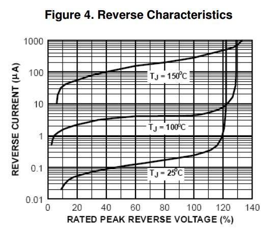
** However, even with a 400V PIV diode, you might just about get away with 500V testing - I did! With a reverse-biased 1N4004 (400V PIV) (and a series resistor!) it was obviously non-conductive at a 250V test voltage. However, somewhat to my surprise it was still non-conductive with 500V across it. Only if I increased the test voltage to 1000V did it behave 'as expected' - the diode starts conducting, with roughly the 'zener' voltage across it, and the meter indicates a lowish IR. However, looking at the data sheet for the IN4004, the 'typical' reverse breakdown ('zener') voltage is shown as something over 480V (120% x PIV) at room temp - so maybe I had a 'good one', whose reverse breakdown voltage was >500V ...
However, it looks as if one could not be certain that the breakdown voltage was going to be much over 480V, so you could be unlucky!
However, last time I tried it, there was too much capacitance (probably in the PIR light fittings) for my MFT to test in teh short time it allows - it did work with dad's old style "press and holt to test" Megger. I've not tried to see if my MFT has the "press and hold for extended test" mentioned in this thread.
Well, as you know, in all the years I've been using MFTs, I hadn't realised, until I was very recently told here, that they have "press and hold for extended test" - and, having looked around, it seems that most/all MFTS (and, I guess, dedicated IR meters) do have that functionality these days! However, even with that functionality, if there is too much initial current through capacitive paths, the meter may 'refuse' to continue the test!

Of course, although the series resistor will protect any rectifier diodes from permanent damage if they are reverse-biased beyond their breakdown voltage, none of this guarantees that other components (e.g. capacitors) in an 'electronics module' won't be killed by 500V IR testing!

Kind Regards, John
 
My plan was to use 250V, or actually 350 since that's about the peak voltage for 240V AC. Working on the basis that if anything can't tolerate that, it shouldn't be connected to the mains anyway. And as I think we've agreed, it's going to be a very special case for the insulation to withstand that but not 500V.
 

DIYnot Local

Staff member

If you need to find a tradesperson to get your job done, please try our local search below, or if you are doing it yourself you can find suppliers local to you.

Select the supplier or trade you require, enter your location to begin your search.


Are you a trade or supplier? You can create your listing free at DIYnot Local

 
Sponsored Links
Back
Top