GQ1

Joined
6 Dec 2020
Messages
9
Reaction score
2
Country
United Kingdom
Hi everyone, long time reader, first time poster. Need some advice please.
We have an old heating system - Baxi bermuda back boiler (serviced every year and running fine), hot water tank, pump and 3 port-valve in the airing cupboard.

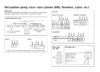
I believe it's a Y-Plan set up. Couple years ago, upgraded the old programmer to the Hive Dual channel reciver. Installed myself and left the old thermostat in situ and just turned all the way up. I believe there may have been bridging in the old programmer, but I think I removed this based on some advice I found online. Currently, the receiver only has the L, N and a wire into both the HW(On) and CH (ON) both HW&CH Off channels are empty. And of course the earth.

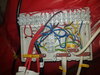
Believe it worked without any trouble, but now I have had to replace my 3 port-valve. I had a Sunvic Duoval (DM5651), mid-position with 5 wires, coloured white, blue, yellow, orange and Earth. I have replaced it with a Drayton (MA1/679-3) Mid- position. Also, with 5 wires, but a grey instead of a yellow. I have tried wiring it in, but have not had any success in getting it to operate as HW only or CH only - I believe the valve is just staying in the mid position. It's brand new, so am sure its my install that is the problem.

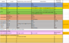
I need some advice as it appears that from the fused wiring box, there should be additional wire coming out of port 18 (see pic) and going to the programmer, but this wire isn't present. I'm thinking from looking at the wiring diagrams, that if I connect the wires in the wiring connector box as follows it might solve the issues, but would appreciate some advice please?

Blue - Blue
Orange- Orange
Earth - Earth
Grey (new) - white (old)
White (new) - yellow (old)

Failing that, I'm thinking of completely removing the old room thermostat wiring and believe that to do this, I just disconnect the wires situated at ports 1;2 and 3 in the fused box and remove them.

Keeping me up at night, so I bow to your greater wisdom - please help!

3port and pump.jpg box1.jpg Close up port 18.jpg Connector box.jpg Existing wiring.jpg Hive programmer.jpg New valve.PNG Old Thermostat in situ.jpg Hive dual channel.PNG
 
Last edited:
Sponsored Links
The mid position 3-Port motorised valve relies upon a 'HW off' signal to move it fully across to the heating only position. This signal comes from two places. The 'HW off' at the programmer [Hive dual channel terminal 1] and also the Hot water cylinder thermostat satisfied terminal. Without a live on its grey wire, the motorised valve will remain in the centre position and not move fully across to 'heating only'. I have highlighted these connections in red on the diagram below.

Capture.JPG


From your other photos, it appears that you have a Relay Junction Box as part of your installation. The wiring is slightly different, but still requires the HW off connection from the programmer / and cylinder thermostat satisfied connection.

10155067.jpg
 
Last edited:
Hi Stem,
Thanks for coming back to me and what a find that diagram is! Thanks!
Looking at it though, I think I am right that the HW Off wire should be originating from port 18 on my Relay Junction Box - by my system doesn't have a wire coming out of this. I have wires coming out of the relay box at ports 7, 17, 19 and 20 - could it be as simple as wiring a third wire in from port 18 to the Hive receiver?

Thanks again by the way - your posts have been a huge help over the years!
 
Unless you are desperate to keep that relay box, it would be far better and probably easier to scrap it, and just install a standard Y plan wiring centre.
 
Sponsored Links
Thanks @GQ1. What you say sounds right, but suggests that wired as it is, it would have never worked properly. However, I'm no expert on the relay box. I have only ever come across one and that was when I was taking it out and converting to a standard Y-Plan exactly as @flameport suggests.

If the relay box is in working order then adding the missing connection should sort it. However, in the long term conversion to a standard Y-Plan would probably be the way to go I imagine sourcing a replacement for the relay box maybe tricky.
 
Hi @flameport & @stem, many thanks for the advice - didn't even consider replacing the junction box. Had a look and seems easy enough with an install of a fused spur and a Y-plan wiring centre. Ordering the bits today and will see how I go this weekend. Thanks again for all the help, really had me stumped looking at it. As you say Stem, it probably never worked properly without that wire and I probably never noticed it before! Will be sure to let you know how I get on.
 
Just looking again at the wiring diagram, the original DM5601 valve appears to be wired differently internally to other motorised valves. I should have guessed that when you said it had a yellow wire instead of a grey one.

upload_2020-12-7_9-20-26.png

The DM5601 has a separate wire for each required position CH only (white) / Mid position (Yellow) / HW only (orange)

Whereas Y-Plan valves receive only two control signals, one from the heating (white) and one from the hot water (grey). When both heating and hot water are required it moves itself to the mid position without a separate connection telling it to do so.

The remaining control wire (orange) is connected to in internal microswitch used to switch the boiler on/off, which in your case is done by the relay box instead.

Therefore I believe that only another replacement DM5061 would be a suitable direct replacement to work with the relay box.
 
Thanks @stem - guess I am going to have to replace the junction box and rewire the lot. I've ordered a Drayton LWC1 wiring box and a fused spur switch. Will give it a go this weekend and remove the old thermostat and wiring. Sure the wife will be happy to have that eyesore off the wall!
Cheers again.
 
Update thanks @flameport & @stem for your advice. Today have managed to remove the old system, isolate and remove the old thermostat and re-wire the system and install a 3amp fused spur switch. All went well and no "pops" or "bangs" along the way. I had a bit of a sticking point where there was no actual wiring clearly identifiable for the boiler. The main wire was a 4 core, with 1 core wired into the original junction box as the "boiler L" and the remaining 3 into L, N and E.

I managed to put it all in and there is power to the pump, 3 port, cylinder stat and Hive Programmer - 1 issue though - as soon as I turn the mains back on, boiler fires up straight away and so does the pump, even if the programmer isn't calling for HW or CH. If I press the CH or HW button on the Hive, the 3 port engages and moves to the appropriate position. Likewise, if I turn the cylinder stat down, the 3 port engages appropriately.

If anyone could offer me advice on this, it would be much appreciated - When I wired the 4 core in, from the fused spur, I used the wiring as per the original junction box - L = L (8), N=N (6), E=E - but then the 4th core, was wired into port 5 in the original junction box, which according to the wiring diagram above is the "pump & boiler L".

Is it possible that I have mixed up the main line and the boilers switched line on the new wiring centre, or could it be something more sinister?

I have a outline of the wiring connections from the old vs new and a photo of the new junction box. I also followed the box wiring instructions for the wiring centre basics and made the links specified with the dotted lines and linked out the room stat.

I've checked and double checked the schematics and I cannot seem to work out what the issue might be.
 

Attachments

  • Wiring plan.PNG
    Wiring plan.PNG
    40.7 KB · Views: 419
  • Wiring centre.jpg
    Wiring centre.jpg
    321.9 KB · Views: 303
  • LWC1 wiring diagram.PNG
    LWC1 wiring diagram.PNG
    99.3 KB · Views: 453
I'm a bit puzzled by the 4 core wire to the boiler you mention. Newer boilers have 4 cores, a permanent live, a switched live, a neutral and an earth. Older back boilers like yours, usually don't have the permanent live and just have L (switched by the controls) N & E. This matches the diagram you posted, where the Permanent L is shown 'dotted' as optional.

Capturea.JPG


In which case the boiler and pump should only get their 'switched live' from the orange wire of the motorised valve and the 'call for heat' terminal of the cylinder thermostat. So that it only fires up when either the hot water requires heating, or the motorised valve moves to the heating only position and makes the orange wire live.

Capture.JPG


I would start by checking that the boiler is connected correctly. One thing that can be tricky even for those of us that see this frequently, is to work out which is the cylinder thermostat 'call for heat' terminal and which is the 'satisfied' terminal. If they are transposed the boiler will fire when the hot water is already hot, but go off when it isn't hot. Or in other words work in reverse.

Unfortunately the wiring centre photo doesn't help much without knowing what is on the other end of each of the wires.

If your boiler does have 4 wires going to it instead of 3, then it would help if we knew what they were connected to at the boiler end.
 
Thank you Stem- am going to dig deeper in daylight and will let you know how I get on. I owe you a pint or 2 one day.
Turns out, I mispoke, it's a 3 core + earth - going to try an isolator switch above the fused spur, as makes sense in my mind.
 
I cracked it! - well, kind of. Was getting feedback from the fused spur I had installed, as it was a 3 core + earth into the fused spur (so doubled up on the L-in / L-out connectors). This caused the boiler to fire as soon as the mains was turned on and the pump to kick in as soon as the fused spur switched on.

I installed a 3-pole isolator switch and removed the fused spur and it worked a treat. Not happy about running it without being fused, so have found a 3-core isolator switch, with a 3amp fuse built in and have ordered it. Should hopefully sort the issue once and for all. Rest of the day gonna cap the old thermostat wires and do some plastering and painting.

Thanks again for all the help! Will sign off again after new switch delivered and installed.
All you had to do was isolate the switched live in the fused spur
 
Sorry I don't understand most of that.

There shouldn't be any feedback. Where is power being fed back from? Everything associated with the heating system should get its power in one way or another from the 'load' side of the same 3A fused spur, in a 'chain' of supply. So, the fused spur supplies power to the programmer, the programmer supplies power to the thermostat, the thermostat supplies power to the motorised valve, and finally at the end of the chain the motorised valve supplies power to the boiler and pump. So that only when the link is completed is power transferred down the chain programmer....thermostat....motorised valve....boiler / pump. There shouldn't be any thing connected that could cause feedback.

I would also be seriously worried that if I understand you correctly, you now have a heating system without a 3A fuse to protect its wiring and internal circuitry. If it's being supplied from the 32A MCB for the socket supply in the consumer unit, and as most of the heating system wiring / components will only be rated at a few amps what do you think might happen if a fault occurred?

Also, why a 3-Pole isolator? There's only one Live and Neutral supply for the whole heating system. Earth wires are permanent connections and not fed via switches. Below is how it should be connected. N L E from the load side of a 3A fused spur. You can have multiple wires in the FCU load terminals, but there shouldn't be any other mains supply into the heating components to cause any feedback.

Capture.JPG
 

DIYnot Local

Staff member

If you need to find a tradesperson to get your job done, please try our local search below, or if you are doing it yourself you can find suppliers local to you.

Select the supplier or trade you require, enter your location to begin your search.


Are you a trade or supplier? You can create your listing free at DIYnot Local

 
Sponsored Links
Back
Top