This contains replies to several posts.
There are three twin & earth cables behind the programmer.
One pair: Providing Live & Neutral for the programmer.
One question answered.

Second pair: The brown wire goes to HW OFF, the blue is on the N terminal for the programmer.
You need to find the other end of this cable. The brown wire should connect to WC/T10. The blue should connect to WC/T2.
I tested brown wire at terminal 1 of the programmer to see if it matched the blue wire at the WC end which was in WC/T6. I'm testing using resistance and I get a figure ~12M ohm. I may be wrong here but I assumed that maybe I've identified that it is the brown wire from programmer/T1 - but perhaps there is some kind of cable fault. Not sure.
I connected the blue wire from WC/T6 to WC/T10 then fired the system up with CH circuit on, HW circuit off at the programmer - demand from the room stat - no demand from cylinder stat. I tested WC/T10 against neutral and got a reading of ~65v.
I repeated the above test but took the blue wire away from WC/T10 and isolated it back at WC/T6.
Readings
WC/T10 against neutral ~65v
WC/T6 against neutral ~20v - if identified correctly and no cable faults I would expect 240v here - fed from programmer T1 for HW OFF.
The third pair are providing CH (BLUE) and HW ON (BROWN) - I managed a continuity test on these earlier today - and the circuits are going on/off with the room and cylinder stat as expected.
Your last diagram shows a yellow wire connected to the programmer. What has happened to it?
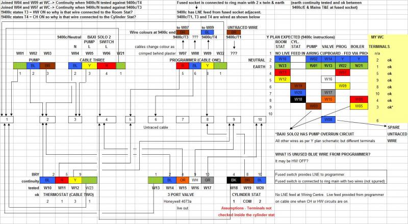
The main picture block shows the wiring I have identified at the wiring centre. The bottom right hand corner shows the wiring numbers & colours at the programmer end. As mentioned earlier I believe I am correct to say:
Programmer T3 CH ON = BLUE WIRE -> RED wire at WC end (W07) from cable one connected to WC/T5 providing 240v for switching through the room stat.
Programmer T4 HW ON = BROWN WIRE -> YELLOW wire at WC end (W09) from cable one connected to WC/T8 and providing 240v for switching through the cylinder stat.
I believe these two wires are correctly identified as I can fire the HW / CH independently - or together by switching the room / cylinder stat demands on/off. Note HW circuit must be on in order to get the CH working as can't get a voltage to the grey wire.
My view is the blue wire in the wiring centre could be connected to the N terminal of the programmer - After isolating the programmer I've tried testing for continuity with both of these neutral wires in case the electrician did something weird with the crimps but can't get continuity.
By N terminal I hope you mean terminal 2. The blue wires connected to other terminals are
not neutrals
To clarify the N terminal at the programmer end (as in ENL1234) - I am not confusing this with the programmer terminals 1234.
There is an earth with the RYB wires from the programmer - this is connected into the wiring block.
Which terminal does it connect to in the wiring centre?
All earth wires arriving at the wiring centre are connected to WC/T1. I have added the wires - and I show that they are connected to WC/T1 in the schematic top right - but I have not drawn the lines in on the circuit diagram. I have not tested the earth wires for continuity at the WC.
What RYB wire are you talking about? You said above that there are three cables to the programmer; none of them has a red or a yellow wire.
Just a thought. Is the RYB cable visible only at the wiring centre end, i.e there is a hidden connection between the brown/blue cables at the programmer and the RYB cable at the wiring centre?
Yes - the cables have been crimped - these joints are somewhere behind plaster in my utility room!
So need to be sure of earth continuity to the rest of the house wiring from the wiring centre, the programmer and the fused spur?
Yes. Terminal one of the wiring centre is the earth point for the pump and the motorized valve so this needs a connection to the main earth, possibly via the programmer or the boiler earth point.
As mentioned I'm fairly confident there is earth continuity from spur to the programmer then through to WC/T1 for the other devices but have not tested this.
The fused spur is right next to the programmer. I checked the wiring for that this morning, there's a twin&earth feed which looks the same diameter as the feed into the programmer - and there's two other heavier t+e cables that suggest the central heating power is on the ring main and not spurred off.
That's no problem.
I think this the source of earth for the HW/CH system - possibly at the boiler end as well but have not opened that up.
I'm beginning to think there is either no spare wire available to take the HW OFF 240v to the airing cupboard - or that I need to find those cable joins and check the original wiring to see if there used to be.
See above.
There is one other possibility that has occured to me. I know there are four wires for the boiler - EARTH, a separate switch live & pump-overun live and also a blue wire that is currently connected to neutral at the wiring centre. I would expect this cable to be routed directly from the boiler to the airing cupboard - but if it was routed via the programmer there is a possibility the neutral wire from this cable (cable three) is connected to terminal 1 at the programmer so the 240v would flow to the neutral block at the wiring centre.
There are three pump connections on the boiler: Live, Neutral and Earth. I think you will find that the blue wire connects to the Neutral. Find the boiler end of the cable and check, it quite easy to do as the same cable has a yellow.
You don't show what the boiler earth cable connects to in your diagram.
As above - all the earths are to WC/T1
Regarding tracing the boiler cable - I checked the blue neutral at the wiring centre end (W04) and this is connected to the N terminal at the programmer - I do not know if the boiler wiring for EARTH, switch live and pump live are routed direct from the boiler to the WC or if they go via the site of the old programmer in the utility room and so are not accessible to me. I do not believe they can come near the new programmer site because the boiler operates correctly and there are no other wires available at the programmer end.
I removed the link between live and terminal one as a chap from Honeywell explained it wasn't necessary to make the bridge as the 9400c provides 240v out on this terminal - the ST1250 didn't.
Correct. The link is not needed.
I tried re-establishing the link to rule out the 9400c being faulty and not providing the 240v from programmer T1. I tested the blue wire at WC/T6 to see the results - no change to any voltages at WC/T10 or WC/T6.
So - now I have the new wiring in place there is just a single wire connected to terminal one that I would expect to connect to the blue wire on terminal 6 in the wiring centre
Terminal 1 of the programmer should connect to terminal 10 of the wiring centre.
I've tried this - see earlier notes - getting a voltage from the blue wire of ~20v - not 240v, suggesting I didn't identify the wire correctly or maybe some kind of fault


")

 Had enough for this evening!