Hi - hope someone can help. ")
I have a three port Honeywell 4073a valve, cylinder stat, Honeywell room stat and Honeywell ST1250 controller.
I tried replacing the ST1250 with a 9400c but can only get the HW circuit to work - no CH. (Note I got the info for the backplate change from Honeywell and have double checked what I did with them).
With the old programmer I can get HW or HW+CH so I assume the controls all work correctly. I also assume that as I have a 3 port system it should be possible to have independent control of the HW and CH circuits (e.g. it is possible to run the CH when HW is off).
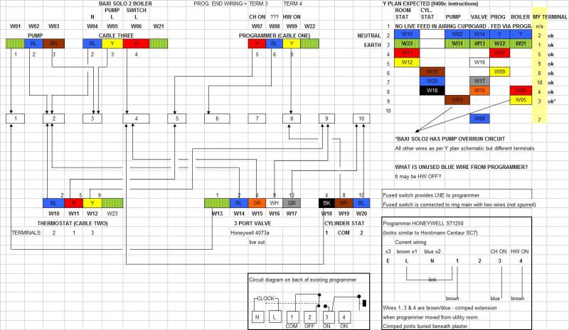
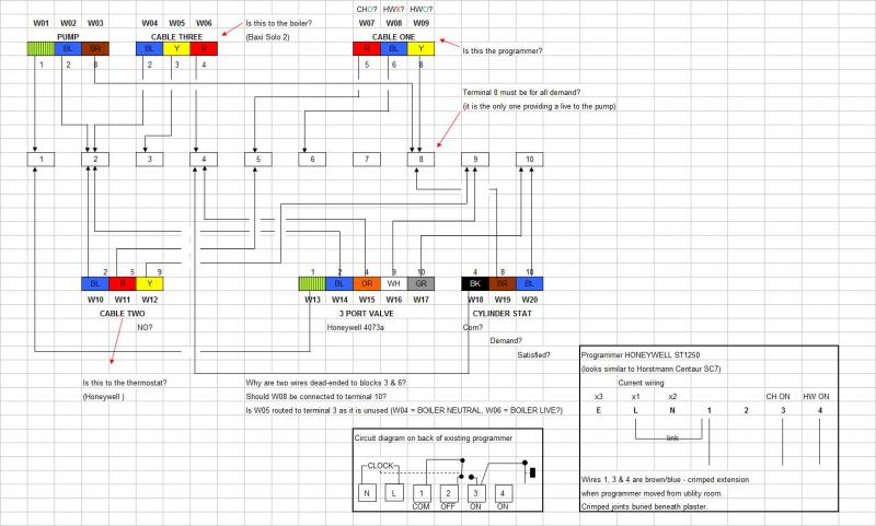
I THINK the problem is the 10 block wiring centre in the airing cupboard - the wiring here doesn't match the Y plan layout supplied with the 9400c. In particular there are two wires which terminate at the block and don't connect with any others - so I assume one of these is the CH ON from the programmer and should be wired differently.
I've made a drawing of the wiring setup together with some info on the current backplate wiring for the ST1250, and a circuit diagram from a sticker inside the ST1250.
I hope the diagram will be easily understood by someone on here who could advise whether my reasoning is correct and offer some suggestions as to how the wiring should be modified to allow the 9400c to work correctly.
Sorry for the long winded post and hope someone has some advice.
Thanks in advance
Colin
I think I've added the image correctly
I have a three port Honeywell 4073a valve, cylinder stat, Honeywell room stat and Honeywell ST1250 controller.
I tried replacing the ST1250 with a 9400c but can only get the HW circuit to work - no CH. (Note I got the info for the backplate change from Honeywell and have double checked what I did with them).
With the old programmer I can get HW or HW+CH so I assume the controls all work correctly. I also assume that as I have a 3 port system it should be possible to have independent control of the HW and CH circuits (e.g. it is possible to run the CH when HW is off).
I THINK the problem is the 10 block wiring centre in the airing cupboard - the wiring here doesn't match the Y plan layout supplied with the 9400c. In particular there are two wires which terminate at the block and don't connect with any others - so I assume one of these is the CH ON from the programmer and should be wired differently.
I've made a drawing of the wiring setup together with some info on the current backplate wiring for the ST1250, and a circuit diagram from a sticker inside the ST1250.
I hope the diagram will be easily understood by someone on here who could advise whether my reasoning is correct and offer some suggestions as to how the wiring should be modified to allow the 9400c to work correctly.
Sorry for the long winded post and hope someone has some advice.
Thanks in advance
Colin
I think I've added the image correctly