Altering three way lighting circuits

bsr

Joined
5 Aug 2008
Messages
970
Reaction score
111
Location
Gloucestershire
Country
United Kingdom
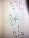
Hi, I have two separate lighting sub-circuits on the same lighting circuit (i.e. same MCB in CU). I would like to do the following:
1. Remove switch 3 (sw3a and sw3b are separate switches on the same 1g face plate).
2. Can remove switch 1 if necessary or keep if easier.
3. Add another new switch in a different place to the others.
4. Have both light fittings switched from switch 2, switch 4 and the new switch.
5. Avoid damaging plaster and disruption as much as possible (wires plastered into walls and tiles above so access will have to be holes into ceiling).

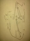
I could run a T&E from switch 4 to a new intermediate switch, then another from the new switch to switch 1, and then a third T&E from light fitting #1 to #2. That would sort the switching but would mean that I was taking the perm live from one light fitting at one end of the room, and taking the switched live to another fitting at another end of the room. That sounds like a bit of a nightmare for the next person who has to come along and fit it.

Any other suggestions? If I try to wire from scratch then I will still have loop/perm live going to fittings where it's not used. I also don't know how the loop runs yet - these fittings are in the middle of the run somewhere but I don't know which fittings are before/in between/after so I can't just rip the unused stuff out and it means I could have loop running through a light fitting that is not being used to switch.

Thought/suggestions please?

switches.png
 
Sponsored Links
Anything is possible - but you need to be more specific about what you want and what you can and cannot do regarding new cables. .

I am puzzled by the fact that while 3a & 3b are the same 2-gang switch, (what you call a loop) is present at 3a and not 3b but 4.
 
I can do whatever I need to do, I'm asking for advice on the easiest!

By loop I mean the perm live radial that goes between each fitting on the circuit. It's often labelled loop on JBs and ceiling roses.

I also thought it's interesting that this isn't the usual way of wiring two way lighting is it? Normally you would take T&E to the first socket then 3&E to the second. They've taken a red 1&E to the first switch, T-E between the switches and then a black 1&E back to the rose. I've not seen this before, nor have I seen a sheathed single plus earth.
 
Last edited:
To save joining the wires in the two way switches this
two-way-plus-inter.jpg
will likely work better, however still need a joint in the intermediate switch.

However using kinetic switches or smart switches you can avoid running cables. To my mind the biggest problem is what it looks like, this 1715717766157.png can allow you to use switches where ever you want, and it is magnetic, so will stick to a steel blanking plate allowing you to have multi controls for same devices around the house, but this 1715717959422.png Quinetic looks more like a traditional switch. And for my bedside I use one of these Remote control.jpgso it is as much down to what it looks like, as to how it works. I used the first example to turn the dinning room lights on/off from a temporary bed, when wife got her knee replaced, however she found voice commands using google Nest Mini's was easier, so it got re-used as a door push for the door bell.

I have a mixture of smart switches, smart relays, smart bulbs, smart TRV's and smart energy monitors which can also switch devices on/off some have been really good, and some have failed, but been using them since around 2017 so some are getting on a bit now. My problem is the floors have been repaired meaning only way to get between floor and ceiling is through the ceiling, so looked for wireless methods.

I don't think I have used a switch for landing light for around a year, simple hey google turn on/off landing light.
 
Sponsored Links
Is it definitely a 2 core and earth between switches?
Can you do pictures of wiring at all switches and light fittings?

Anything is possible but we have to have the full information to give decent advice.
 
Is it definitely a 2 core and earth between switches?
Yes. Red 1 core and earth to first switch, red & black twin and earth between switches, and either red or black 1 core and earth from final switch back to the switched live terminal in the rose.

Example picture showing 1 core black and earth.
 

Attachments

  • DSC_0717.JPG
    DSC_0717.JPG
    279.5 KB · Views: 17
Last edited:
Can you do pictures of wiring at all switches and light fittings?

How about these, I had omitted some detail for clarity. As above I don't yet know if the live/loop runs directly between the two ceiling roses of if there is another light in the way. I don't have a continuity tester so I think that will require live testing - disconnecting all the wiring at each fitting and seeing which other fittings still have power.
 

Attachments

  • DSC_0715.JPG
    DSC_0715.JPG
    233 KB · Views: 21
  • DSC_0714.JPG
    DSC_0714.JPG
    185.3 KB · Views: 19
Your original (blue) sketch doesn't agree with the later version.

Ultimately you need to achieve something like this
1715905454461.png

A lot depends on the easiest way to run the new cables on which sequence switches; 2, new and 4 are, it could be; new, 2, 4 or 2, 4, new etc.

Switches can also remain at 1 and 3 if that makes it any easier for cable runs, for example
1715906372310.png
 

DIYnot Local

Staff member

If you need to find a tradesperson to get your job done, please try our local search below, or if you are doing it yourself you can find suppliers local to you.

Select the supplier or trade you require, enter your location to begin your search.


Are you a trade or supplier? You can create your listing free at DIYnot Local

 
Sponsored Links
Back
Top