Auto air bleed valves; when do they work?

Joined
6 Sep 2008
Messages
2,334
Reaction score
258
Country
United Kingdom
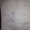
My air source heat pump is mounted on the wall outside about 3 metres up. The flow comes in at ceiling level, down to a diverter valve that chooses DHW or UFH. In DHW mode it runs round s coil in the adjacent tank and returns. In UFH the flow drops to ground floor level and splits, one to ground floor UFH manifold, the other way up to the manifold on the first floor.
Both the manifolds have Auto bleed valves on them, and are less than a year old. Occasionally a fault of no flow/no water in the circulator is logger by the heat pump. I'm able to get things running again by leaving the system to sit in a fully inactive state for a while (overnight) then opening all UFH circuits and setting both UFH pumps on max (they're normally on 1-2 out of 7) and power cycling the heat pump. A long sequence of gurgling and whooshing noises and the fault normally clears. I think it's fair bet that the pump in the HP got air locked and the UFH pumps were enough to drag fluid through, but this system has been in constant op for at least 6 months so I was hoping there wouldn't be much air left. The manual bleed points I have available never have any air in them. I don't know if there is s bleed valve in the pump itself and I have a concern that it's naturally a high point in the system because of how its plumbed (the DHW diverter being lower means air in the HP wouldn't naturally drift into the upstairs UFH circuits?) so ultimately I'm wondering how to get the blenders I have to expunge the air I have- do they work if the pumps are pumping fluid constantly or do auto blessed need periods of inactivity in the system to allow bubbles to write into them and not get pumped past them?
 

Attachments

  • image.jpeg
    image.jpeg
    82.1 KB · Views: 148
Last edited:
Sponsored Links
Occasionally a fault of no flow/no water in the circulator is logger by the heat pump

I assume the system is pressurised and around 1 bar?
There should be air venting locations at high level. If not fitted to the appliance then fitted by the installer. The installation manual might make some mention of it.
What heat pump do you have?
 
Pressurised and circa 1 bar when inactive and cold, 2 bar when active, pump is a vaillant vwl125 (actually made by toshiba-carrier)
I'm not sure whether it has a bleeder inside, though I'm not averse to removing the cover

Edited first post to add a sketch of the heights of certain components
 
Should be a method fitted to enable the air to be vented at the phe.
One would have to have a look inside the casing. Don't worry its won't reveal a combustion chamber.
But if you feel your not up to it then call a professional. Or post up an image.
 
Last edited:
Sponsored Links
Annoyingly, it's never been the weather/ideal light conditions to crack open the casing and look for a bleed valve (it's half way up a wall, in the outside world).

Pretty sure an air-to-water heat pump doesn't have a combustion chamber though, thankfully! :)
 
The air pot on auto bleed valves often has a cap that needs unscrewing a little ( and leaving thus ) to let the air escape - like a car tyre valve.
 
Yes.. These ones have a grey knob on the side that (according to the installing plumber) is the auto bleed; the car tyre dustcap looking thing is the manual bleeder, sprays glycol out when I slacken it, so it seems there's no/never air in the pot. I'm not sure if this is because it never gets in there or if the grey knob (which is left slack at the moment) already vented it

There's an awful lot of gurgling from this system to say the bleeders never have air in them. makes me wonder if it's getting stuck somewhere else that doesn't have a bleeder but perhaps should


Last night the no-flow error on the heat pump bit me again and I couldn't get it shifted. Setting both UFH pumps to max seemed to realise enough flow through the heat pump to fool the flow sensor into thinking that there was enough flow for the compressor to produce heat, but the flow must have been slower than normal because the delta T was much greater: 11 degrees between flow and return against the default 7.. As soon as I did anything that reduced the flow (close UFH loops, drop UFH pump speed, activate DHW mode, reduce the manifold TRV from full open) the error symbol would return on the heat pump..
From this I surmised that the internal circulator pump on the ASHP wasn't working, and it was just luck that the two UFH pumps could drag enough fluid through to fool the flow sensor. I couldn't see how an airlock could have caused these symptoms either, so i just turned the system off (UFH pumps powered down, heat pump left on but in fault mode and inactive) and left it overnight

This morning the house was very quiet so perfect opportunity to have another play. The heat pump has some test modes where you can force things to activate. I enabled the test for "force the circulator pump to run" and immediately heard water whooshing noises (only faint) and the flow error cleared. The system's been running normally since so I'm a bit puzzled; i was certain that the circulator pump inside the ASHP was stuck or inoperative last night but this morning it was producing flow just fine on its own, without help from the UFH pumps (still powered off).
Can an airlock cause this behaviour? Can it be possible to have 3 pumps in a flow/return configuration system (see image in first post for diagram of heights), one is airlocked and doesn't pump anything but the other two aren't airlocked and can pump, yet they cannot clear the air lock from the third pump? What did leaving it overnight do?
 
You need to have someone have a look at it. Air will collect at the highest point.

Remember if they are going up ladders and working at heights be sure they wear safety harnesses or hire a scissor lift.:D
And keep a good sharp stanley knife to cut them free from the harness for when they fall and get hung up.
 
I have two thoughts/queries!

Firstly, the expansion seems excessive. Somewhere you will have an expansion vessel. This is usually sized at about 12% on the total system volume. But much more relevant is the air charge pressure on it. So a typical expansion vessel on a house might be 8 litres or 12 litres.

Normally on a gas system from 10 C to 80 C the pressure increase would only be about 0.3 bar from 1.0 bar.

You may want to investigate this either with the installer or using the FAQ on this site. Nevertheless, I don't see any obvious connection between this and the air problem you have.


Secondly, the concern should be exactly where is this air entering in your pressurised system. In a pressurised system its difficult to think of any way that air could enter. In unpressurised systems then air can be sucked in from a leak near a pump suction connection. But with normal domestic circulators the suction is weal compared with the system pressure.

If we were to assume that it is not air but other gasses caused by corrosion, usually mostly hydrogen, then that indicates a serious problem which needs attention because all the rad pinhole! You can test for hydrogen by bleeding towards a lighter flame which will light hydrogen !

The system should have been inhibited when installed. The installer SHOULD have removed the label from the inhibitor and dated it and stuck it somewhere easily visible!

You don't mention but there would normally be bleed points, usually auto, at the heat pump as its a high point. You seem to imply that you don't often visit it because of its high up location.

Tony
 
Well, it's only been in about 10 months. The cooling circuit is filled with the recommended ratio of Fernox HP5c, all underfloor, estimated system volume 260 litres, I think the EV is either 12 or 18 litres - it was sized and supplied by the installers. It's hard to imagine a corrosion cause as 95% of all the internal surfaces of the system are plastic (ufh pipes) with a small amount of copper, stainless and brass making up the rest. HP5c has a suitable inhibitor in it I think.

There are 3 bleed points I know of for certain: one on each UFH manifold and another copper dead leg with a "bicycle valve" installed by the engineer that fitted the system. The manual says there is an an additional BV inside the heat pump (outside, on a wall):

http://www.centralheating.co.uk/system/uploads/attachments/0000/4876/geoTHERM_air_manual.pdf on page 8, says it does have one (component #9)

I don't know how/if the layout of that diagram relates to the actual component positions; I last had the covers off the heat pump when I was playing electricians mate, wiring the control switching into it ages ago. It's now half way up a wall and would require a ladder and some lift/twist to access it; my back is currently capable of neither.. (and at less than a year old, I'm not certain I should be fiddling with that aspect!)
 

DIYnot Local

Staff member

If you need to find a tradesperson to get your job done, please try our local search below, or if you are doing it yourself you can find suppliers local to you.

Select the supplier or trade you require, enter your location to begin your search.


Are you a trade or supplier? You can create your listing free at DIYnot Local

 
Sponsored Links
Back
Top