CMT927 wiring - sanity check please - SORTED

Joined
1 Mar 2011
Messages
859
Reaction score
19
Location
Telford
Country
United Kingdom
Hi

Before I go ahead and plug everything in, I wanted to double check I have it right, hope thats ok.

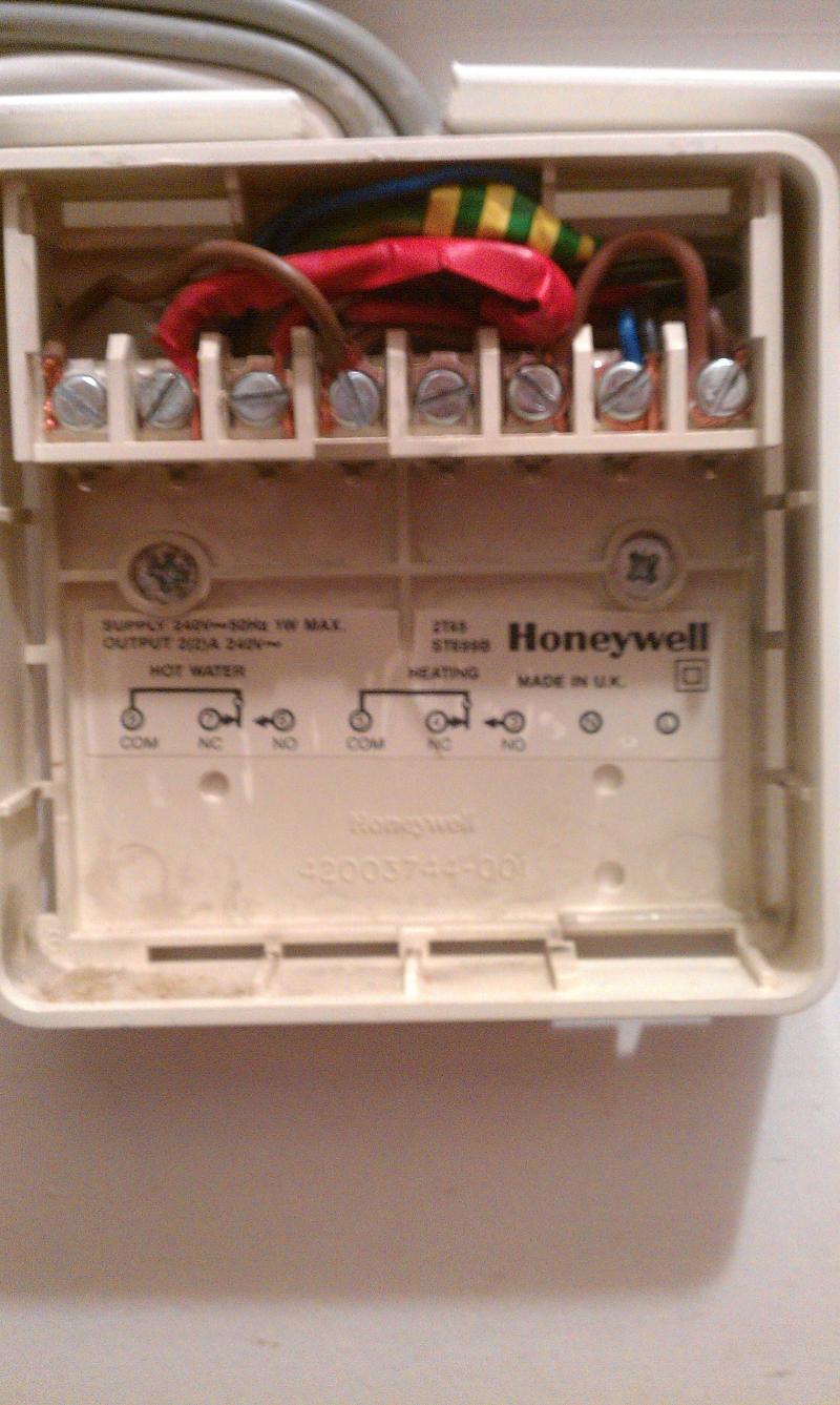
I have a open vented y plan system, old ideal mexico 2 boiler, and a wiring box near the 3-way valve, st699b controller.

I have evidence to suggest there was originally a wireless stat in place before i moved in btw (sticker found in close proximity explaining pairing, rawl plugs near wiring box with nothing fixed but approx the right size, etc).

So looking at the wiring box, everything seems to tally in terms of:

Mid-pos valve white wire goes to number 5 on chocblock
What I think is the controller cable has a wire going to number 4 on chocblock
Numbers 4 and 5 on chocblock are bridged with a 2 inch wire.

Am I correct in saying that A/B on CMT927 relay box are to replace the existing bridge on 4/5 of the chocblock and thats it?

Only thing i'm concerned at is that whilst there are a heap of neutrals hanging off number 2 of the chocblock, number 1 which is supposed to be perm live has nothing in it. With the ST699b heating and water set to off, number 8 is live (which goes to the cylinder stat).

I can find a perm live elsewhere, but i'm wondering if it was done this way as the whole system seems to be powered by a single 3 amp plug downstairs next to the boiler, including the st699b, boiler, wiring centre etc.

Am i on the right track please?

Thanks
Mike
 
Sponsored Links
OK so I found something that looks simpler, posted by D_hailsham

This is the standard wiring for a Y-plan, using a 2 channel programmer and a traditional thermostat. You need to make the following changes:

(w/c = junction box aka wiring centre)

Remove the connection from ST9400 CH ON to w/c terminal 4

Ignore completely the connections for the T6360 Room stat

Connect CM927 L terminal to the w/c live terminal (normally terminal 1)

Connect CM927 N terminal to the w/c neutral terminal (normally terminal 2)

Connect CM927 B terminal to same w/c terminal as valve white (normally terminal 5)

Link CM927 L to CM927 A terminal.

(Edit 4/2 11: This diagram is now the correct one for a boiler with pump overrun.)

View media item 30148

This is for a pump over-run system - does it matter that my boiler doesn't over-run?
 
The only permanent live feed (without bringing a second supply in) I can find is a black wire which has red tape around it, and goes to pin 7 HW Off/Grey wire for the 3 port - is that OK to use? It comes out of a cable which has a second wire, a red, which seems to be the neutral and goes to pin 6 Cylinder stat/HW ON - no idea why the red and black are mixed up (confirmed via 0v between known neutral and suspected neutral, and 249v between known neutral and pin 7, and pin 7 and suspected neutral).

So is it ok to run the permanent L needed by the relay module off Pin 7?
 
The only permanent live feed (without bringing a second supply in) I can find is a black wire which has red tape around it, and goes to pin 7 HW Off/Grey wire for the 3 port - is that OK to use?
No, you can't use pin 7 as it only has 240V on it when HW is OFF or the HW stat is satisfied (open).

It comes out of a cable which has a second wire, a red, which seems to be the neutral and goes to pin 6 Cylinder stat/HW ON - no idea why the red and black are mixed up (confirmed via 0v between known neutral and suspected neutral, and 249v between known neutral and pin 7, and pin 7 and suspected neutral).
Colours mean nothing. Both Pin 6 and Pin 7 can be live. Pin 6 when the HW stat is calling for heat; pin 7 when the HW stat is satisfied.

So is it ok to run the permanent L needed by the relay module off Pin 7?
Definitely not; you will have to get a permanent live from somewhere else. If the ST699 is near the junction box, you could grab a supply from the feed to the chock block from the L and N Terminals.

Wiring of a boiler without pump over-run is slightly different. There also differences for the CM927 as follows:

Connect B to 5
Connect A to 4
Connect L to A
Connect L to permanent Live
Connect N to Neutral
Disconnect the connection from ST699 CH ON to terminal 4

View media item 31288
 
Sponsored Links
Hi - thanks for the reply.

I went ahead and connected it up via pin 7 and whilst it seems to be working now, I can see from your post that its not the correct way to do it.

Before I started this, pin 4 and 5 were bridged - presumably in lieu of a room stat would that be fair to say?

Currently, i have it as follows:

Connect B to 5 - done (white connection for valve)
Connect A to 4 <--- not done this, because there is nothing else connected to 4 when the ST699 CH ON is removed.

Connect L to A - done
Connect L to permanent Live - connected to pin 7 but i see will remove this.
Connect N to Neutral - done
Disconnect the connection from ST699 CH ON to terminal 4 - done

The ST699b is downstairs and the wiring box/valve/relay are upstairs. There is a plug nearby that I can use, but thought it would not be best to import a new live into the system - unless I can remove the L-A connection and keep the power feed to the relay box seperate from the A/B switch side?

Thanks !


EDIT: I guess I could make use of the now redundant CH ON wire as a live feed, as its now not needed?
 
OK so what i've gone ahead and done, is disconnect the CH ON from pin4 in the 10 way chocblock and connect that to pin 1. I have connected the L of the relay to Pin 1 in the chocblock.

At the ST699 connector panel i've put a bridge between permanent L and "CH NO" (red - same wire - now becomes permanent L for chocblock pin 1).

Is that OK?

Or should I remove the connection from "CH NO" from the backplate and connect directly to the L connection?

In other words I am unsure how "CH NO" now being permanently live will affect the ST699 - does it matter?

BTW can the battery be replaced in the ST699?

Thanks!!


Like this:

 
Before I started this, pin 4 and 5 were bridged - presumably in lieu of a room stat would that be fair to say?
That's correct. The previous owners have removed the stat and put the link in it's place. Incidentally, you should inform your Solicitor because, unless the previous owners stated on the Fixtures, Fittings and Contents Form that they were removing the stat, the previous owners are in breach of contract.

Connect B to 5 - done (white connection for valve)
Connect L to A - done
Connect N to Neutral - done
All OK

There is a plug nearby that I can use, but thought it would not be best to import a new live into the system
NOT a good idea. The system should be fed from a single source.

I guess I could make use of the now redundant CH ON wire as a live feed, as its now not needed?
That's the solution!
Move wire on 4 to 1 (chockblock)
Move wire on CH ON to L (ST699)
Connect L (Relay) to 1 (chockblock)

Awesome!!! Thanks - all sorted.

Cheers
 
Just in case anyone is considering the cm927/cmt927, I have had it installed a day and it is GREAT. There was no room thermostat previously, and honestly I didn't realise how quickly the rooms heat up and how hot the living room gets.

Its a 36kw boiler powering 15 rads, one of which is 17000btu in the living room - last year we struggled with the heat because it would get so hot in there and the TRV didn't seem to do much - like it was responding too slowly.

Having played about with the system yesterday, got the room upto 23c and it was too hot, but not as hot as we had it last year - heating was only on for a short while, boiler switches off then and just stayed off for whole evening. We would have had it on constant previously. Room was still 20c this morning, so boiler didn't kick in.

I need to tune up/balance the system but already I can see this was £104 well spent.

Many thanks to D_Hailsham !!

Cheers.
 
Its a 36kw boiler powering 15 rads, one of which is 17000btu in the living room
That nearly 5kW. Are you sure? It would have to be a 2.8m long 600mm high K2 (double with fins on both elements) to give that output.

The boiler sounds mighty large, even for 15 rads - unless it's a combi boiler.
 
Its a 36kw boiler powering 15 rads, one of which is 17000btu in the living room
That nearly 5kW. Are you sure? It would have to be a 2.8m long 600mm high K2 (double with fins on both elements) to give that output.

The boiler sounds mighty large, even for 15 rads - unless it's a combi boiler.

Yep thats it precisely, 2.8m x 600mm, double rad, double fins. Bet it weighs a ton - stelrad, listed as a K2. I priced one up as it was getting a little rust on a corner.. think i'll get some paint lol.

EDIT: Not a combi, its a floor standing Ideal Mexico 2. Seems to be in good nick, just about to get its annual service. She likes the juice, quarterly gas bill for jan/feb/mar last year was north of £500. Hence the room stat!
 
Not a combi, its a floor standing Ideal Mexico 2.
15 rads does suggest a large house and 5kW in one room implies poor insulation. However you boiler may still be oversized. Use the Boiler Size Calculator to find out what size boiler you should have.

Thanks, but i've no intention of replacing the boiler until it dies. The room insulation is fine, its one of the warmest houses i've lived in tbh.

The room in which the big rad is located is fairly large at approx 7mx5m,3m. A room size calc came out around (iirc) 15-16k btu so its about right.
 

DIYnot Local

Staff member

If you need to find a tradesperson to get your job done, please try our local search below, or if you are doing it yourself you can find suppliers local to you.

Select the supplier or trade you require, enter your location to begin your search.


Are you a trade or supplier? You can create your listing free at DIYnot Local

 
Sponsored Links
Back
Top