
Combining cold feed and vent to prevent pumping over

Joined
17 Jun 2015
Messages
33
Reaction score
2
Country
United Kingdom
My mother keeps getting air in upstairs radiators. It's a vented system, but was converted from a gravity type when the previous boiler was installed. The previous pumped system seemed to work fine for many years, but she had a new boiler installed 2 years ago and the new layout has resulted in water being pushed back up the cold feed and air being sucked down the vent pipe. The upshot is that I am regularly bleeding her bathroom radiator when it becomes cold due to being full of air.

The new Worcester boiler uses the same pump as the previous system with some minor mods to the pipework. One anomaly is that the previous layout only allowed the CH to be on while the HW circuit was active, so the guy who fitted the Worcester installed a wireless thermostat to overcome the missing cabling required between the boiler on the ground floor and HW cylinder on the first floor and he installed a second 2 way valve on the HW return pipe near the boiler. The cold feed pipework is mostly hidden under floorboards and there is a horizontal run of around 7 metres from HW cylinder to the boiler where the pump is.

A different plumber who serviced the boiler recently, said he could try to reconfigure pipework near the pump to stop the pumping over and he came back yesterday to do this. However, it turns out that the pumping over is actually via the cold feed to the F&E tank when we had assumed it was the vent pipe. With the cold feed so inaccessible, he proposed fitting an expansion vessel near the boiler and converting to a sealed system, which I understand may cost £1000. My mother now wants to cut her losses at 2 hours labour costs from yesterday and I suggested getting an oil filled electric radiator for her bathroom instead.

Now I am reading that electric heaters in bathrooms may conflict with electric regs, so am trying to find a cost effective solution for her. Research using AI came up with a suggested simple solution of combining the cold feed and vent pipes by teeing into the vent pipe just below the F&E tank in the loft. This sounds like an ideal solution, but I'm wary that AI often misses key points and comes up with wrong suggestions, which is why I'm hoping an experience UK qualified heating engineer can confirm whether this should work.

Can anyone here advise please?
 
Last edited:
My combined cold feed & vent from new has worked perfectly, with some rads over 40 years old, water is perfectly clear/clean with the odd (very) drop of inhibitor added via a rad now and then. The circ pump is installed on the return just before the outside heatpac oil boiler, the 6M pump runs at around 3.0M head in PP (proportional pressure) mode.
The vent on mine carries on up and over the F&E cistern.

Can you post a photo of the vent and cold feed and pump with its mode and setting, you say "he installed a second 2 way valve on the HW return pipe near the boiler", it may have no bearing on the problem but the 2 way valve is normally installed on the HW cylinder coil inlet.

This is from your "New Boiler Nightmare", can you clearly point the cold feed and vent.

1793892958559.png


1793891746910.png
 
Last edited:
Wow, forgotten that I already posted about this installation on here! Yes, you are correct John, thanks for taking the time.

I can take some photos at the weekend. You can see the vent pipe in that photo behind the pump in the far corner of the cupboard. The unpainted pipework above the pump is heating and HW flow, heating return pipe on the far left, HW return in the middle with the newer 2 way valve on. The nearest point when the cold feed pipe is visible is next to the HW cylinder about 6 metres along on the next floor.

In the previous configuration, the HW 2 way valve was upstairs by the HW cylinder, but I think it was moved to the boiler cupboard to facilitate powering the wireless thermostat receiver from the main wiring centre.

The plumber who serviced the boiler had assumed it was pumping over via the vent pipe due to the pipework configuration, whereas instead we found water entering the F&E tank from the cold feed. The vent pipe is positioned normally above the tank and I think the cold feed is 22mm copper pipe.

The pump has 3 settings and I've tried them all: it's a large house with old, slightly constricted 15mm copper pipes that have been power flushed. Setting 1 on the pump takes ages to warm the rads up, so I've been leaving it set on 2. As things are, one upstairs radiator ends up cold every few weeks until bled.
 
Last edited:
Is the vent the white pipe just to the right of the hand wheel on the pump inlet (bottom) isolating valve?.
The cold feed isn't visible in the photo??, where is it teed into the system, is it into the cylinder coil return maybe?
 
Yes, that's the vent pipe. The cold feed is miles away near the HW cylinder, but not sure whether before or after it.
 
If the cold feed is teed in to the cylinder coil return then you can IMO get pump over/back through the cold feed when there is no demand for HW as the (new) 2 way valve will prevent any cold water head necessary for the pump, and the HW coil circuit will be under pressure from the pump when HW only in service. When you get a chance have a look and see where the cold feed is teed in. In a close coupled system its teed in between the vent and the pump and no more than 150mm from (downstream of) the vent, ie, in your case, between the vent and the pump inlet valve.

You could just drain down until the level is a little below the bottom of the F&E cistern, then cut the cold feed where it's connected to the cistern and, like mine, connect a short piece of pipe from the cold feed to the vent pipe adjacent to the F&E cistern, you could then cap the now cut off cold feed but with a manual air vent, essential to get rid of air when the system is refilled etc, ideally, the cold feed should be cut off where its teed into the system but should be OK and can always be reversed if any problems with your now combined cold feed and vent.
 
From what I can see it looks like the pump and zone valves are in the wrong position. The pump should be after the vent and inlet and then bypass and valve's.
It looks like your system is pumping into the inlet and vent
 
Perhaps the 2 way valve on the HW return pipe is back pressurizing the hot water primary circuit and pushing water up the cold feed, in which case it makes sense to utilise the vent pipe for the cold feed, because it's much closer to the pump anyway and does not seem to pump over. Putting an air vent on the capped end in the loft also sounds like a good idea.

So hopefully I'm finally understanding this correctly: air is being drawn back into the system by pressure fluctuations caused by poor pipework geometry and some thermal contraction. Connecting the cold feed to the vent pipe near the loft maintains a reasonable head of system pressure while allowing for expansion and because the vent pipe now has a water supply, it sucks water into the system instead of air and the problem is solved. Is that right?
 
From what I can see it looks like the pump and zone valves are in the wrong position. The pump should be after the vent and inlet and then bypass and valve's.
It looks like your system is pumping into the inlet and vent
Yes, it has been botched. There's a lot of detail and history about this on my other thread from a couple of years ago.
 
From what I can see it looks like the pump and zone valves are in the wrong position. The pump should be after the vent and inlet and then bypass and valve's.
It looks like your system is pumping into the inlet and vent

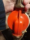
Easy enough to check that out by holding a mirror behind the pump, if its pumping (correctly) upwards, the inlet (nozzle) will be pointing down as shown in the photo, there should also be a arrow on the pump body to show its orientation. No harm also to ensure that the Boiler HW flow pipe is connected to the pump.

Perhaps the 2 way valve on the HW return pipe is back pressurizing the hot water primary circuit and pushing water up the cold feed, in which case it makes sense to utilise the vent pipe for the cold feed, because it's much closer to the pump anyway and does not seem to pump over. Putting an air vent on the capped end in the loft also sounds like a good idea.

So hopefully I'm finally understanding this correctly: air is being drawn back into the system by pressure fluctuations caused by poor pipework geometry and some thermal contraction. Connecting the cold feed to the vent pipe near the loft maintains a reasonable head of system pressure while allowing for expansion and because the vent pipe now has a water supply, it sucks water into the system instead of air and the problem is solved. Is that right?

Even if the HW zone valve was not in the return but the cold feed is teed into the coil return, pump over through the vent or pump back through the cold feed can still occur due to the differential pressures, that's why the Vent & Feed are kept as close as possible.
If you do opt for the combined I would suggest that you install a lever or gate valve on and very near the ball cock mains supply, after any drain down then just crack that open and refill the system slowly, you won't have much problem with getting rid of any air then. Also latch open the two zone valves before refilling (or draindown).
 

Attachments

  • Pump Orientation.jpg
    Pump Orientation.jpg
    360 KB · Views: 17
Yes, in that photo it's pumping upwards towards the Honeywell valve. Now that I know the pipe in the background partially obscured by the pump is actually the vent, it becomes obvious it won't pump over since it's on the suction side.

Therefore using the vent as a combined feed will address the fundamental problem of having the cold feed so far from the pump by effectively relocating it to the inlet side of the pump. I assume the existing configuration worked for the original gravity system, but whoever converted it to a pumped system didn't take this into account or didn't bother due to the difficulty in getting a cold feed from the F&E tank to the boiler.

Many thanks for your help John and I also note your point about fitting a valve on the ballcock - presumably to minimise backfilling pressure down the combined pipe which could prevent air from escaping.
 
Here's another combined set up. Like mine, it carries the vent up and over the F&E cistern but strictly speaking a true combined vent and cold feed does not have a vent but I prefer the type with the vent pipe carried on up and over, don't know if its any advantage or not.

1793965196616.png
 
Yes, that's what I'll try to do, except that photo shows another pipe entering the tank at mid level: I'm guessing that is the original cold feed pipe having been reconnected to the tank - possibly to assist with filling next time the system is drained. I guess it will also let trapped air escape from the old cold feed pipe, but wouldn't you be worried about the connection at the tank leaking if it's below water level (it looks like a standard ballcock inlet)?
 
Thinking about this set up again, I wonder if there's a simpler solution:-
The main problem to resolve is air getting into the system, which is being drawn in through the vent pipe. We know that (I think only when the boiler is starting up) water is being forced up the cold feed into the F&E tank and because that amount of water exceeds the capacity of the vent pipe, when the system stops and cools, it draws all the water in the vent pipe plus some air into the system.

Why can't I simply extend the vent pipe so it is submerged in the tank? That would still allow it to vent and at the same time result in water being drawn back instead of air.

I would love to hear any comments on this - might even give it a try tomorrow with some push fittings to see if it works.
 

If you need to find a tradesperson to get your job done, please try our local search below, or if you are doing it yourself you can find suppliers local to you.

Select the supplier or trade you require, enter your location to begin your search.


Are you a trade or supplier? You can create your listing free at DIYnot Local

 
Back
Top