consumer unit info

Joined
20 Nov 2023
Messages
5
Reaction score
0
Country
United Kingdom
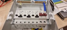
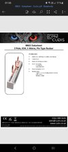
I have a Cudis Titan consumer unit that I want to install into my campervan. It came with a 100A isolation switch already installed. I have included a picture. Am I right in thinking the letter next to the 100 is L N for line and not IN for in. I have also included a picture of the DP busbar.

And if this is the Live side how would I wire the RCBOs up to this switch. I have been told to use a DP busbar but if this is the live side the Live and Neutral would be the wrong way round to marry up with the RCBOs

The RCBOs are Cudis DP type A, curve C. Thes are the large 2 way type without the earth and neutral fly leads.
 

Attachments

  • 20231106_002514.jpg
    20231106_002514.jpg
    164.4 KB · Views: 61
  • Screenshot_20231117_015517_Word.jpg
    Screenshot_20231117_015517_Word.jpg
    99.2 KB · Views: 60
Last edited:
Sponsored Links
In = rated current or current setting of protective device.

It has nothing to do with neutral or in.

Type C means between 5 and 10 times the thermal rating to trip the magnetic part of the trip, so would need a loop impedance better than 1.44 Ω which seems unlikely on any camp site, also having a 48 amp supply would be unusual, 16 amp is the norm, so would have expected two x 10 amp and one time 6 amp for the RCBO's as likely the camp site MCB/RCBO will trip first, and one does not want to have to go to the reception to get it reset, better if your trips open first.
 
Last edited:
In = rated current or current setting of protective device.

It has nothing to do with neutral or in.
So can I wire the live and neutral the same orientation as the RCBOs, and connect them with the DP bus bar
 
Sponsored Links
Yes, there are a number of short forms used with electrics section from BS 7671 here
1700468762976.png
If is also not if they are just the international standards organisation list for short forms.
 
In = rated current or current setting of protective device.

It has nothing to do with neutral or in.

Type C means between 5 and 10 times the thermal rating to trip the magnetic part of the trip, so would need a loop impedance better than 1.44 Ω which seems unlikely on any camp site, also having a 48 amp supply would be unusual, 16 amp is the norm, so would have expected two x 10 amp and one time 6 amp for the RCBO's as likely the camp site MCB/RCBO will trip first, and one does not want to have to go to the reception to get it reset, better if your trips open first.
Many thanks for your reply, so changing them to a 6 and two 10A would be better.

So can the isolation switch be wired the same orientation as the RCBOs enabling me to use the DP bus bar.
 
Many thanks for your reply, so changing them to a 6 and two 10A would be better.

No.

1. Eric has not seen that they are RCBOs
2. He has also gone off on a tangent that while technically correct has little relevance to you, because:
3. If they were not RCBOs, then the correct thing to so, would be to change them to RCBOs or the main switch to RCD, not slighly downrate overcurrent devices, so that instead of there being a 99.9% chance of not having effective fault protection, is only actually 99.8%

So can the isolation switch be wired the same orientation as the RCBOs enabling me to use the DP bus bar.

Yes, unless either pole has any markings we cant see to specify which way round to utilise the poles
 
No.

1. Eric has not seen that they are RCBOs
2. He has also gone off on a tangent that while technically correct has little relevance to you, because:
3. If they were not RCBOs, then the correct thing to so, would be to change them to RCBOs or the main switch to RCD, not slighly downrate overcurrent devices, so that instead of there being a 99.9% chance of not having effective fault protection, is only actually 99.8%


Yes, unless either pole has any markings we cant see to specify which way round to utilise the poles
Thanks for that Adam, I can not see anything to indicate which way around Live and neutral would go. Just has terminals numbered 1and 2, 3 and 4 which I'm guessing indicates the line in goes to the top of isolator. Which would suggest to me the busbar would go to the bottom connecting isolator and RCBOs, and load out of top of RCBOs.
 
No.

1. Eric has not seen that they are RCBOs
2. He has also gone off on a tangent that while technically correct has little relevance to you, because:
3. If they were not RCBOs, then the correct thing to so, would be to change them to RCBOs or the main switch to RCD, not slighly downrate overcurrent devices, so that instead of there being a 99.9% chance of not having effective fault protection, is only actually 99.8%


Yes, unless either pole has any markings we cant see to specify which way round to utilise the poles
Thanks for that Adam, I can not see anything to indicate which way around Live and neutral would go. Just has terminals numbered 1and 2, 3 and 4 which I'm guessing indicates the line in goes to the top of isolator. Which would suggest to me the busbar would go to the bottom connecting isolator and RCBOs, and load out of top of RCBOs
 

DIYnot Local

Staff member

If you need to find a tradesperson to get your job done, please try our local search below, or if you are doing it yourself you can find suppliers local to you.

Select the supplier or trade you require, enter your location to begin your search.


Are you a trade or supplier? You can create your listing free at DIYnot Local

 
Sponsored Links
Back
Top