Controlling Omnie UFH with Nest - wiring (including bonus question!)

Joined
4 Aug 2017
Messages
73
Reaction score
1
Country
United Kingdom
Hi all,

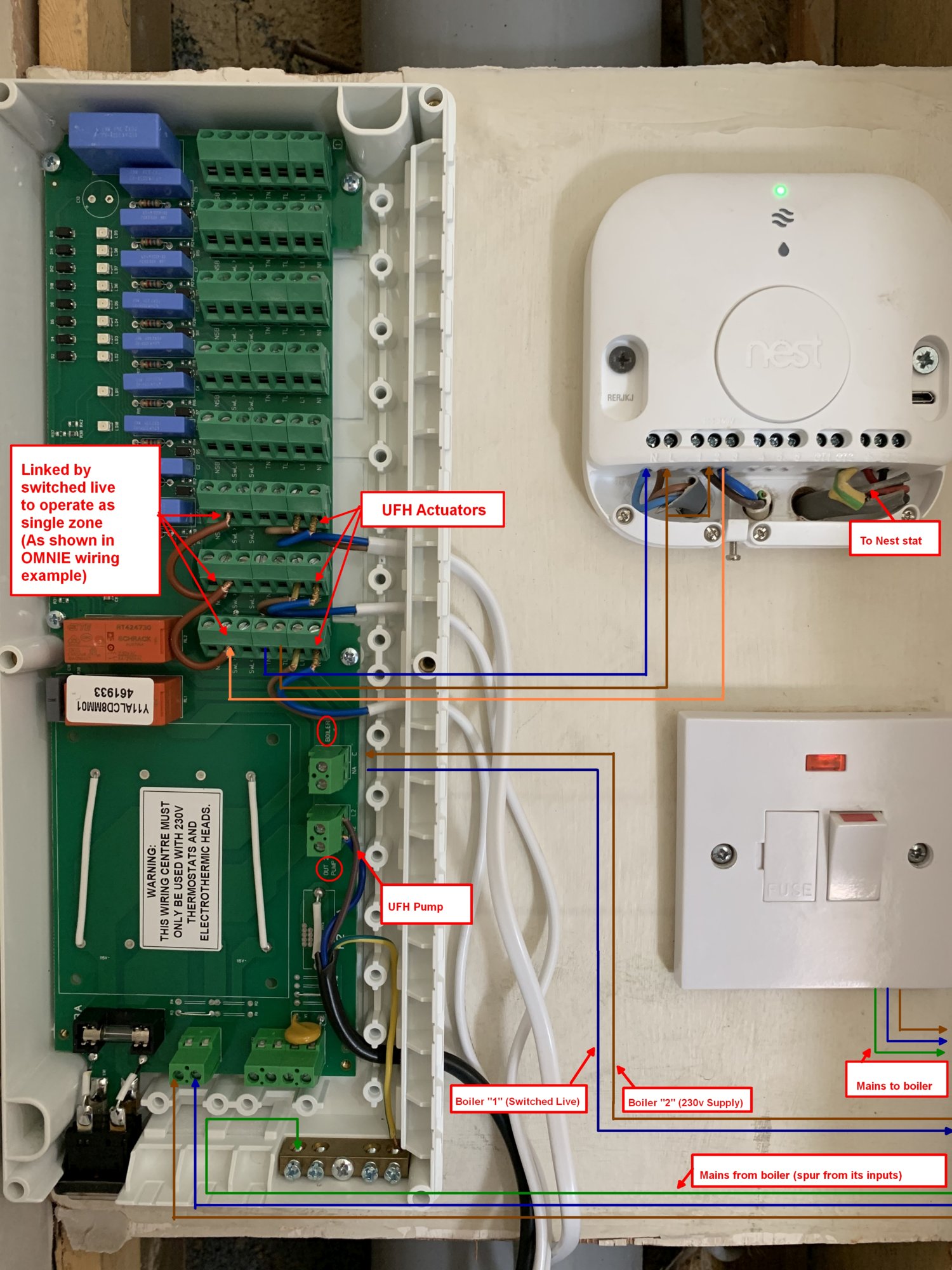
I have an existing Baxi EcoBlue Advance combi boiler controlled by a Nest 3rd gen via Heat Link.

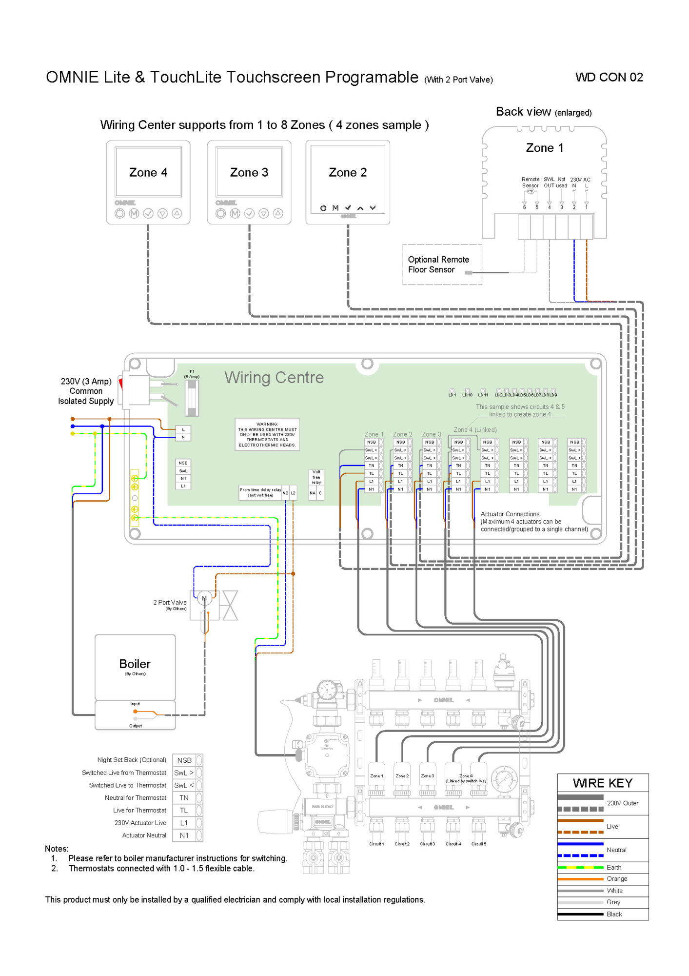
I’ve just installed an Omnie UFH system (wet, boiler fired) and am trying to connect up its wiring centre, with it being controlled by the same Nest (as opposed to Omnie’s own thermostat). So one thermostat for the whole house including the UFH.

At the moment it works from a plumbing perspective without the wiring centre, but I have to turn the UFH pump on/off manually, rather than it kicking in when the Nest calls for heat and fires up the boiler.

So the bonus question first:
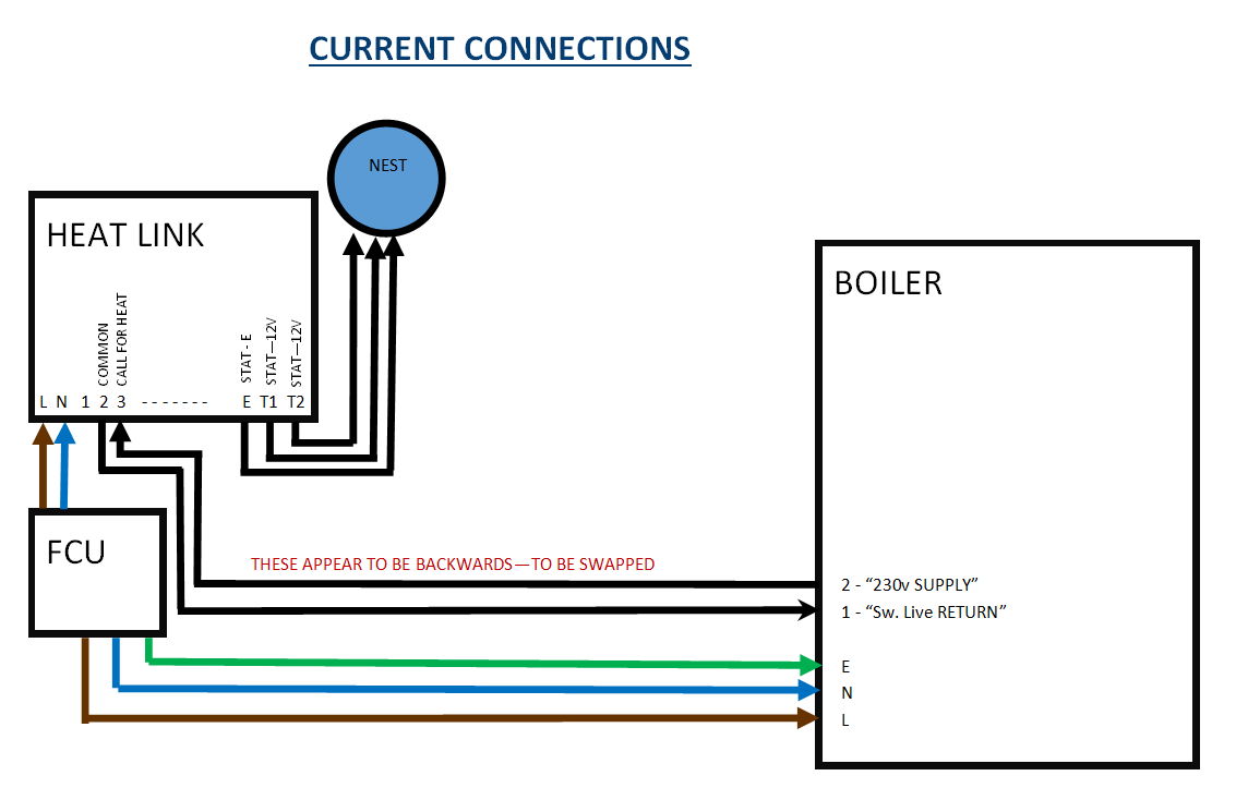
While reading up on this I was looking at the connections from Heat Link to the boiler (starting at the beginning!) and they seem the wrong way around from the docs I’ve read?

So I have:
Heat Link connector 2 > Boiler connector 1
Heat Link connector 3 > Boiler connector 2


The Nest manual states:
Connector 2: Heating relay common
Connector 3: Heating relay normally open/call for heat


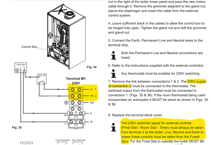
And the boiler manual, for its connectors:
“The 230V supply at connection 2 must be connected to the thermostat. The switched output from the thermostat must be connected to connection 1”

Am I reading this wrong? Shouldn’t the boiler connection 2 be going to the Heat Link’s Common, and the call for heat going back to the boiler’s connection 1?

If so, how is the boiler working normally now?!

I was quite close (I think!) to understanding how the Omnie would wire in until I saw this but maybe I’m misunderstanding how the switched lives work?

thanks!
 
Sponsored Links
A quick follow up:

blog post (which in turn references an older DIYNot thread) suggesting the wires should be connected the opposite way to mine:

https://www.linuxtutorial.co.uk/install-nest-heat-link-thermostat-with-a-baxi-duo-tec-combi-boiler/


Also, thinking about this, in my situation both the boiler and the Heat Link are powered independently from a fused spur (the boiler does not supply power to the Heat Link).

so the only direct connections between the Heat Link and boiler are those two wires.

that being the case, if we’re talking about a basic switched circuit, does it even matter which way around the wires are? Are they just forming a loop that closes when there’s a call for heat?
 
It is volt free connections so as long as heat link 2 and 3 are connected to boiler b1 and bk2 it does not matter which goes to which.

The basic idea with any modulating boiler is to allow the boiler to modulate, as far as I can see from instructions the boiler only has an electrical on/off control, it does not use OpenTherm, so the idea is Nest runs the boiler for as long as it can, without the boiler cycling too often, unfortunately Nest does not connect to any TRV head so they simply need matching to Nest as best as you can, I have the same problem but to lesser extent, as my boiler does not modulate.

I seen no reason why the UFH pump should not come on with the boiler, but clearly the TRV heads in each room are still controlling room temperatures, but in rooms with the UFH the radiators will be running cooler, and likely the by-pass valve will still allow hot water to return to boiler like it always did and cause the boiler to modulate.

Just remember the TRV head controls the room temperature and boiler output, the Nest thermostat is only to stop boiler cycling and turn off heating when your not at home. It does not control room temperatures. The theory was Nest sends a wifi signal to the Energenie TRV heads which follow Nest, however Nest withdrew their support, and if you link the TRV heads to Nest when you change the temperature on your phone the linked TRV heads go to same temperature as Nest, however if you turn the Nest dial or set a schedule on Nest, I found the Energenie TRV heads did not follow. Maybe it is just mine? But I gave up, and removed the Link, and simply set the same schedule on both the Nest and Energenie TRV heads, so if I want to alter Nest manually also need to alter TRV head manually, I find leaving house the geofencing and occupancy detection turns off boiler, and in the main I have returned before the house has cooled enough to switch Nest on, I could also set the Energenie TRV heads using IFTTT to also use geofencing, but found it is really not required.

Since UFH takes so long to heat and so long to cool it really would not work with geofencing and occupancy detection so if it were me I would set it up so it can be switched off but would simply run normally at same time as boiler. So line from b 1 to switch and then to UFH pump so pump can be off when you don't want UFH but normally it will work same time as boiler.

However I have not read up on the new energy saving pumps,
The new style pumps are simple to use, have 3 different speed setting and an EEI value of ⧠0.23. They reduce the energy consumed by automatically adjusting the pump speed to suit the heating load and run in the most energy-conscious fashion. The use of this pump can save up to ¬£40 a year on the energy bill.
this may mean no need to supply pump from boiler, but I left fitting central heating systems before 2013 when new rules came in.
 
A quick follow up:

blog post (which in turn references an older DIYNot thread) suggesting the wires should be connected the opposite way to mine:

https://www.linuxtutorial.co.uk/install-nest-heat-link-thermostat-with-a-baxi-duo-tec-combi-boiler/


Also, thinking about this, in my situation both the boiler and the Heat Link are powered independently from a fused spur (the boiler does not supply power to the Heat Link).

so the only direct connections between the Heat Link and boiler are those two wires.

that being the case, if we’re talking about a basic switched circuit, does it even matter which way around the wires are? Are they just forming a loop that closes when there’s a call for heat?
There has been some debate, but in the main all central heating stuff at 230 volt is fed from same supply, I know there are pairs of AA cells all over the place so with my system I have 10 supplies, but we don't count the TRV head batteries so all 230 volt should come from a single supply normally a FCU, I know with Nest it is volt free so really does not matter, but standard practice has always been one FCU to supply all central heating.
 
Sponsored Links
@ericmark , thanks for this - lots of good info there! Ok...

It is volt free connections so as long as heat link 2 and 3 are connected to boiler b1 and bk2 it does not matter which goes to which.

So to confirm, I could swap the two wires over between Heat Link and boiler to get them matching what seems to be "standard" installation, without risk of frying anything?
One thing - when you say they're 'volt free' connections, why does the boiler manual call its connection 2 a "230V supply"?
An image from the manual:

full


RE the TRV heads - we're just using standard TRV heads on the rads, so no Energenie or smart ones. We do pretty much use the Nest as a room stat that we can control from our phones. Then we balance the radiators with their flow control / TRVs to get the house to heat up evenly.


so all 230 volt should come from a single supply normally a FCU, I know with Nest it is volt free so really does not matter, but standard practice has always been one FCU to supply all central heating.

So this is what we have now, in effect - one FCU supplying Nest Heat Link's N,L,E directly with one cable, and a separate cable supplying boiler's N,L,E.
There's then a third 2 core (&earth but earth unused) flex between the boiler and Heat Link, as discussed, doing the call for heat switching).
I think supplying the boiler and Heat Link off one FCU maybe isn't regs, but this will be getting fixed when we renovate the room the boiler is in.


The UFH's wiring diagram seems to suggest running L,N,E from the FCU to its own wiring centre, then everything else can draw power from there.
But that's phase two of this thread, once I've confirmed what I've already got...!

Thank you again
 
Volt free means the contacts are not connected to the same supply that works the thermostat, so contacts could be 12 volt 24 volt 230 volt DC or AC the heat link is volt free so does not matter. With Hive duel wall thermostat the supplies are linked, so next thought is not so much what is there now as what may be fitted latter.

This looking after the next guy is some thing you can debate, an example personal safety switches should be red or yellow, machine safety switches often black, so removing a black switch may cause damage to the machine but not the guy working on the machine, however because some one fitted a black switch instead of red, I now have a mauled hand. And that was just the wrong colour.

So we can say next person should test, but we expect people to follow convention, so when we switch off the FCU by the boiler and we see the boiler switch off, we expect any thermostat or motorised valve to also be dead as well. This house when bought had three FCU's and a 13A plug feeding the central heating, and you could turn on boiler from the programmer, but to get central heating to work, you had to walk outside, and down a set of steps and into a flat under the house and plug in the pump. Not like that now.

If some one injured then likely you will still be OK, but if some one dies, then they look at everything, lucky that is rare, but the Emma Shaw case they worked out what every tradesman had done, and how each error had added up to the death, the guy sent to prison had not even visited the house, he simply sent some one the courts felt was not trained to a level required.

So in all likelihood even with 10 FCU's supplying the system it will work OK, and I can't actually find a regulations to say whole of central heating must come from a single protective device, but common sense says you want to flick one switch and whole system dead, and I don't mean the main isolator coming into the house even if flicking it isolates all.

The reason it took a 5 year apprenticeship was we were taught how to assess risks and use our skill, but it seems government want children to stay in school longer, so to finish an apprenticeship by 21 means it is shorter, so less it taught, so people rely on the regulations, there is an idea that it can't be dangerous or it would not be allowed. People generally take less care.

We have all seen the temporary become permanent, all well and good testing to see if some thing works, but the measure twice cut once is also true, I will admit when doing my central heating I was not sure how many wires I needed so run a few extra, but I also spent a long time drawing out how it would be wired and still made a mistake.

So ended up with this C_Plan_My_HouseD.jpg before I started to wire it up, my thoughts are I am 69 now, in 10 years time could I remember how I wired it? So planned out I have a chance I can pass this on to some one else. I would say you need to do the same, and once drawn out you can post it on here so any errors can be found, I have needed to add relays to that diagram as not plumbed as I expected.

But you have in your mind what you want the UFH to do, personally I would go other direction, and go for fan assisted radiators to speed up heating, not UFH which is slow, but that is a personal preference, nothing wrong with UFH in a home heated 24/7 and it is what I would select for example in a care home.
 
what model of omnie control centre do you have ?

Hi, it's the DS-EWC1 wiring centre

thanks

EDIT

Just opened it up again and realised that it does have what's labelled as "Volt Free Relay- Boiler" as well as the mains live output that goes to the pump.

The wiring diagram I got with the Omnie is not particularly specific (it shows the boiler connected to the mains live output along with the pump, via a 2 port valve. Obviously we're not using this as it's a combi)

So theoretically to loop the UFH into the controls, I could disconnect the Heat Link from the boiler and connect it to the Omnie Zone instead, then connect the boiler to the "Volt Free Relay", and the Heat Link should activate the UFH and boiler together when it calls for heat?
 
Last edited:
Yes that would work although I would separate the ufh from the rads with a couple of 2 port valves and use two separate stats (two nests or whatever stat you like)
 
Yes that would work.

Excellent, thank you. So this just leaves one question regarding the Heat Link's connection to the Omnie Wiring centre:

All of Omnie's wiring diagrams presume you're using their own controls (of course), and have this kind of wiring at the zone terminals:

L1 and N1 go to their zone actuators, so that's fine.

Am I right in thinking that TN and TL would go to the Heat Link's mains power input, instead of the FCU powering it currently?
If so, their diagram has only one Switched Live coming back from the thermostat, so in this case, what goes to the Heat Link's common connector? Should I use the 'Switched Live To Thermostat' connector on the Omnie wiring centre? Or, I've also seen suggestions that you could bridge the Heat Link's Live internally into its Common?
 
Last edited:
Am I right in thinking that TN and TL would go to the Heat Link's mains power input, instead of the FCU powering it currently?
If so, their diagram has only one Switched Live coming back from the thermostat, so in this case, what goes to the Heat Link's common connector? Should I use the 'Switched Live To Thermostat' connector on the Omnie wiring centre? Or, I've also seen suggestions that you could bridge the Heat Link's Live internally into its Common?

Either of these will work, probably linking the live and common in the heatlink would be easier.
 
Great, I think I'm understanding this now, but am still working on drawing out a diagram beforehand, and will post that asap.

What's the recommended way of powering all this, if adhering to EricMark's advice of having 1 FCU switch for the lot? The boiler's manual advises to power it directly, and I've seen recommendations to spur back off the boiler's mains connectors to power a stat. With that in mind would this be best?


FCU > Boiler L/N/E

Then from Boiler L/N/E spur to the Omnie Wiring Centre's power input?

Then the Heat Link gets is power from there?
 
it really does not matter as long as the whole system can be isolated from a single FCU.
 

DIYnot Local

Staff member

If you need to find a tradesperson to get your job done, please try our local search below, or if you are doing it yourself you can find suppliers local to you.

Select the supplier or trade you require, enter your location to begin your search.


Are you a trade or supplier? You can create your listing free at DIYnot Local

 
Sponsored Links
Back
Top