
Need to defo do some designing with this... I would potentially have access on some sides, one has a roo above where I can put psu in floor void and access from above, other has utility room where I can mount psu against the other side of the wall. Above kitchen i can hide at top of cabinates, skylight I have no idea... Unless I have an access panel on the side of the upstand somehow..

You are using an out of date browser. It may not display this or other websites correctly.
You should upgrade or use an alternative browser.
You should upgrade or use an alternative browser.
DMX Lighting?
- Thread starter unclebob1
- Start date
The skylights would most likely be an access panel in the next joist over from the skylight- main issue is compromising the ceiling insulation as well as having to derate cables due to running through said insulation. Or (if the skylight frame is quite thick- 40mm or so- you could make a false top or bottom wall (25mm depth) and hide everything in that. In that scenario you'd need somewhere to dump the heat from the PSU. If you haven't installed the skylight yet, make sure that the top (or bottom, doesn't matter much which) noggin is set well below (or above) the window to give you space for Gubbins and false wall. But yes, you need to think about this scheme rather carefully before installed Things turn it into even more of a nightmare.
Think your scheme is going to be difficult to assess without eyeball input- it's all going to come down to detail rather than broad brush overviews. But have a go with pictures,m what's to lose ")
Here's the pics:
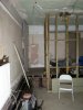
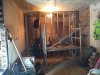
842 is the view of the utility room
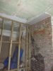
643 is the corner of the utility room where most of the other electroncs will be sited (patch panel, alarm etc)
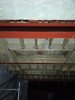
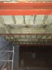
627 is the view of both skylights from the existing room (living room on plan)
315 is both walls against utility
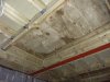
552 is a closer pic of the skylight.
Its a cold roof, so insulation will be going in under.
842 is the view of the utility room
643 is the corner of the utility room where most of the other electroncs will be sited (patch panel, alarm etc)
627 is the view of both skylights from the existing room (living room on plan)
315 is both walls against utility
552 is a closer pic of the skylight.
Its a cold roof, so insulation will be going in under.
Attachments
Last edited:
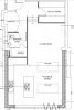
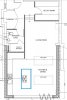
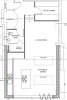
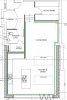
and the plans.
So the island one - (blue lines), the splashback (maroon) and kitchen (purple) should be powered easily from within the units, with one large, or multiple psu's at 1m, 1.5m,2m etc...
The perimiter for some parts should be ok - above the kitchen, the wall against utility room, and possibly the wall shared with bathroom. The rest of that one - ie the long plain wall, and across the doors will be problematic. Doors there is a possibility of servicing from outsite - though then although covered, there will be the possibility that the electronics side will be in a possible damp area...
Distance between the skylight closest to the living room is approx 1m away from a steal beam holding up the old house wall, so possible to push cabling through to floor void in the upstairs room for that one, but not for the other...
Attachments
The kitchen bit is a flat roof extension yes? Control gear on the roof would be a possible but it'll look a bit rubbish from the (presumed) window looking out from upstairs into the garden and of course it would involve penetrations through the roof covering which might or might not be a goer.
You could put boxes on the outside walls but again it'll look a bit industrial (and that assumes the outside walls aren't party walls)
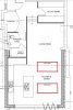
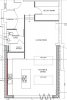
Everything north of the steel (which I've assumed sits on that nib on the west on your pics) plus 2000 down the east wall and the northern skylight can be powered from gear trays under the floor of the room above.
The problem areas are the southern skylight, the southern 3 metres of the eastern wall and the eastern 2 metres above your folding doors.
2 choices;
1) Bite the bullet on chunky power cables and drive them from boxes above the kitchen cupboards. You can push 4 amps for 5 metres down 2.5mm T & E so you'd need a lump of 2.5 from your PSU to each pair of strips. Going to be messy..... actually it isn't that bad, you just end up with 6 x 2.5 running from above the southern kitchen units- 3 to the southern skylight (6 strips), 1 to the eastern 2 metres above your door and 2 to the southern 3 metres of the east wall. And if you fuse appropriately on top of the kitchen cupboards (5A for each leg) you'll get good fault discrimination as well. In fact you could run the northern skylight with the same scheme (from above the cupboards) if it was easier- another 3 x 2.5.
2) Hide some gear up in the ceiling with an access hatch
Data-wise remember you can't spur off the daisy chain (well you can but you'll end up with duplicate addresses which will be a bore). I'm assuming that the drivers on those strips can drive across 5 metres or so, might be worth checking with manufacturer/supplier. As long as they will do that trick then you'll need 2 bits of CAT5 from each skylight either to the eastern wall (to insert them in that chain) or back to the top of the kitchen cupboards (to insert in the chain there). Not sure if the Pi can generate multiple streams- if it can then you only need 1 bit of CAT5 from each skylight back to the Pi (as well as the CAT5 feeding the main chain of course). You are having wall units above the sink aren't you?- if not then oops.
One other possible cable saver would be to run the power in at 12v and then hang DC-DC converters off the 12v lines at every 2 strips or so. Advantage- removes any potential volt-drop problems (you will get some drop even at relatively low current at 5v). Disadvantage- cost and another thing to go wrong.
You could put boxes on the outside walls but again it'll look a bit industrial (and that assumes the outside walls aren't party walls)
Everything north of the steel (which I've assumed sits on that nib on the west on your pics) plus 2000 down the east wall and the northern skylight can be powered from gear trays under the floor of the room above.
The problem areas are the southern skylight, the southern 3 metres of the eastern wall and the eastern 2 metres above your folding doors.
2 choices;
1) Bite the bullet on chunky power cables and drive them from boxes above the kitchen cupboards. You can push 4 amps for 5 metres down 2.5mm T & E so you'd need a lump of 2.5 from your PSU to each pair of strips. Going to be messy..... actually it isn't that bad, you just end up with 6 x 2.5 running from above the southern kitchen units- 3 to the southern skylight (6 strips), 1 to the eastern 2 metres above your door and 2 to the southern 3 metres of the east wall. And if you fuse appropriately on top of the kitchen cupboards (5A for each leg) you'll get good fault discrimination as well. In fact you could run the northern skylight with the same scheme (from above the cupboards) if it was easier- another 3 x 2.5.
2) Hide some gear up in the ceiling with an access hatch
Data-wise remember you can't spur off the daisy chain (well you can but you'll end up with duplicate addresses which will be a bore). I'm assuming that the drivers on those strips can drive across 5 metres or so, might be worth checking with manufacturer/supplier. As long as they will do that trick then you'll need 2 bits of CAT5 from each skylight either to the eastern wall (to insert them in that chain) or back to the top of the kitchen cupboards (to insert in the chain there). Not sure if the Pi can generate multiple streams- if it can then you only need 1 bit of CAT5 from each skylight back to the Pi (as well as the CAT5 feeding the main chain of course). You are having wall units above the sink aren't you?- if not then oops.
One other possible cable saver would be to run the power in at 12v and then hang DC-DC converters off the 12v lines at every 2 strips or so. Advantage- removes any potential volt-drop problems (you will get some drop even at relatively low current at 5v). Disadvantage- cost and another thing to go wrong.
The kitchen bit is a flat roof extension yes? Control gear on the roof would be a possible but it'll look a bit rubbish from the (presumed) window looking out from upstairs into the garden and of course it would involve penetrations through the roof covering which might or might not be a goer.
- Not keen on holes in the roof – rather not have leds then another area of potential water ingress!
You could put boxes on the outside walls but again it'll look a bit industrial (and that assumes the outside walls aren't party walls)
- The east wall is party so no go there unfortunately.
Everything north of the steel (which I've assumed sits on that nib on the west on your pics) plus 2000 down the east wall and the northern skylight can be powered from gear trays under the floor of the room above.
- Yep, defo a possibility as that floor will be coming up for rewire and plumb upstairs
The problem areas are the southern skylight, the southern 3 metres of the eastern wall and the eastern 2 metres above your folding doors.
2 choices;
1) Bite the bullet on chunky power cables and drive them from boxes above the kitchen cupboards. You can push 4 amps for 5 metres down 2.5mm T & E so you'd need a lump of 2.5 from your PSU to each pair of strips. Going to be messy..... actually it isn't that bad, you just end up with 6 x 2.5 running from above the southern kitchen units- 3 to the southern skylight (6 strips), 1 to the eastern 2 metres above your door and 2 to the southern 3 metres of the east wall. And if you fuse appropriately on top of the kitchen cupboards (5A for each leg) you'll get good fault discrimination as well. In fact you could run the northern skylight with the same scheme (from above the cupboards) if it was easier- another 3 x 2.5.
- This is doable at present – the celings are open so can run cabling in the voids, poping out at intervals, im hoping that I can have a faked dropped celling – something like :
https://www.google.co.uk/url?sa=i&rct=j&q=&esrc=s&source=images&cd=&cad=rja&uact=8&ved=0ahUKEwjW6uXAjpXKAhXCKg8KHRY6AfwQjRwIBw&url=https%3A%2F%2Fwww.pinterest.com%2FCWCElectric%2Fliving-room-lighting%2F&psig=AFQjCNH4DOSK4mgrc38sttzbSwXi-T_2-g&ust=1452167176019662
which will hide the run and connection
2) Hide some gear up in the ceiling with an access hatch
Think the wife has already veto’ed this – no hatches in celling…
Data-wise remember you can't spur off the daisy chain (well you can but you'll end up with duplicate addresses which will be a bore). I'm assuming that the drivers on those strips can drive across 5 metres or so, might be worth checking with manufacturer/supplier. As long as they will do that trick then you'll need 2 bits of CAT5 from each skylight either to the eastern wall (to insert them in that chain) or back to the top of the kitchen cupboards (to insert in the chain there). Not sure if the Pi can generate multiple streams- if it can then you only need 1 bit of CAT5 from each skylight back to the Pi (as well as the CAT5 feeding the main chain of course). You are having wall units above the sink aren't you?- if not then oops.
- This is something which I have had issues with, a lot of people had problems but that may be due to fast refresh/frequency, others have successfully run the full 5m. I guess I need to buy and test. Builders will be running CAT5 everywhere anyway - whats another few runs! If need be a couple of pi's to run different areas... There will be wall units - but short ones! Far southwest will be fridge freezer so hiding above/behind that will be the case.
One other possible cable saver would be to run the power in at 12v and then hang DC-DC converters off the 12v lines at every 2 strips or so. Advantage- removes any potential volt-drop problems (you will get some drop even at relatively low current at 5v). Disadvantage- cost and another thing to go wrong.
So this is also a possibility, if I can find small enough 12v-5v converters, they may be able to be hidden in the “fake” edge ceiling.
Alternativly i could hide something like this in the void of the fake ceiling? only issue would then be the two sky lights, which i could put the psu on the east wall and pass the cable though?
http://www.amazon.co.uk/DEOK-Switch...qid=1452082398&sr=1-6&keywords=230ac+to+5v+dc
or
http://www.allpsu.co.uk/Data_Sheets/FullyEnc/25_299Watts/Rs-50.pdf
end up with a fair few of them 8 for the ceiling and skylight but would negate the pushing around of dc everywhere?
http://www.amazon.co.uk/DEOK-Switch...qid=1452082398&sr=1-6&keywords=230ac+to+5v+dc
or
http://www.allpsu.co.uk/Data_Sheets/FullyEnc/25_299Watts/Rs-50.pdf
end up with a fair few of them 8 for the ceiling and skylight but would negate the pushing around of dc everywhere?
Last edited:
So each bit of t+e should be connected to the led strip at 2m intervals if i understand correctly, so feeding 1m each way?
And at 5v, the length of t+e shouldnt be more then 5m?
Looking at suppliers drawings, you can link 2 strips together for power. So if you had 10A available (4mm cable to cross 5 m) you could run 2 strips downstream and 2 strips upstream from a single point. If you only have 5A available then you can only run 2 strips so yes 1m each way will reduce the current running in the strips themselves.
Your switch mode PSUs- stuff like that needs to be accessible so that when it fails you can get at it to fix it or replace it. Plus it'll get warm so would need airflow. That is a fairly compact device, if you could mount it on the surface where you can get at it (and it gets some ventilation) then yes it'll save you some 5v cabling. At the cost of a lot of 240v cabling, you'd need one of those for each strip! Given you have access to the ceiling void at the moment, I'd be tempted to throw the 2.5mm low voltage cabling in, it'll be cheaper and keeps the component count down.
Similar issues with my DC-DC converter idea- I was thinking PCB type devices but they're going to be too expensive for the current you want. CPC do some cheap car USB sockets (same job-12v in, 5v out) so for £5 you could hang one of them on the end of 12v 2.5mm and run 4 strips instead of 2. Big deal. You'll need a 12v PSU at the source end (cost) so all you're really saving is 5m of 2.5mm cable, which costs a lot less than £5. And you'd have to take the thing to bits and put it in a smaller neater box. Unless you want cigarette lighter sockets all over your new ceiling?
You really need to get yourself a couple of these strips and a 5v PSU and do some experiments-
1 Stick 5v up 5m of 2.5mm to both strips, see what the volt drop is like, see if the things work properly. Try extending the 2.5mm, see what happens with regard to cable temperature and volt drop (I'm going from TLC's calculator so no liability for it not working).
2 Stick 8m of CAT5 into the first strip from your controller. Then stick 8m of CAT5 between the end of the first strip and the start of the 2nd strip. Do they both work properly? If not then shorten the cables and repeat.
3 With the above setup running (a test pattern of some sort) create some electrical interference (power drill, vacuum cleaner, fluorescent light switching on/off, a MIG welder working if you have one handy) and see if you get any data errors (should manifest quite visibly). If you do get errors, try shorter links, screened cable or the balanced setup that bernardgreen mentioned. Or decide that you can live with the error level perceived.
If you don't get errors then increase the length of the data cables and repeat (just to see how resilient the setup is).
Your Google link to suspended ceiling didn't work so can't see what you're planning. But given your room width is about 4m I reckon your best most cost-effective plan for power is PSUs (switch mode or proper transformers, whatever) on top of the kitchen cupboards and loads of 2.5mm through the timbers to the targets. Burying cable is fine, burying components like PSUs etc where you can't get at them without ripping holes in the ceiling is a very very bad idea.
Sorry the link is:
http://blog.lightopiaonline.com/lighting-articles/does-your-lighting-make-you-feel-old/
top one - purple looking.
so something like this in the corner:
http://blog.lightopiaonline.com/lighting-articles/does-your-lighting-make-you-feel-old/
top one - purple looking.
so something like this in the corner:
Attachments

Each to their own....... strikes me there's a bit of space in that pelmet, possibly enough for some mains and some small power supplies between the light strips and the wall, as long as they're slimline you shouldn't see the shadowing from the room. Depends how high your ceilings are, ah boo, just checked the pics again, looks like about 2600 so maybe not as much dead space as I'd thought. But I reckon you'd get away with a 25mm high PSU or 10 against the wall, no-one normal is going to see it unless they stand on the worktop.
Definitely room there for the data cabling, also room there for (if you want to go this road) 1mm flex or T & E from an FCU in a corner somewhere going to slimline transformers dotted around the place. 1mm flex at 240v will carry enough current to do the job, you can use normal choc block boxes to link the transformers to the flex, transformers and joints are all accessible for repair/replace/ventilation, it'll be a LOT cheaper and neater. That PSU you linked to from Amazon looks good (except for the open frame), or you could run 2 strips from this little puppy http://cpc.farnell.com/powerpax/ptd-0505pa/5v-5a-ac-dc-switch-mode-power/dp/PW02604 at £14 (there are probably cheaper available on Fleabay).
Doing it with lots of little PSUs is going to cost more than one big PSU for sure but it'll save you having to run a forest of T & E through the ceiling joists. Are you having the same pelmet arrangement round the inners of the skylights?- if so then you're laughing, if not then put the skylight PSUs in the east pelmet and run DC cabling through the rafters- since you're down to 3 metres you only need 1.5mm cable for 4 amps (2 strips).
Rather than using standard 2.5mm² mains cable give some thought to distributing the 12 volt ( or 5 volt ) supply using flat ribbon cable constructred from layers of insulated copper tape such as
http://www.ampetronic.co/Products/O...tion-Accessories/Flat-Copper-Tape-18mm/FB1$18
This has 1.8mm² copper and is only 0.25mm thick per conductor so stacking 4 on top of each other will give you twin 3.6mm² "cable" about 1mm thick.
Other suppliers produce tapes with larger cross section area.
http://www.ampetronic.co/Products/O...tion-Accessories/Flat-Copper-Tape-18mm/FB1$18
This has 1.8mm² copper and is only 0.25mm thick per conductor so stacking 4 on top of each other will give you twin 3.6mm² "cable" about 1mm thick.
Other suppliers produce tapes with larger cross section area.
oldbutnotdead - celing height is a bit of a wierd one - at the joint with the house its about 2.6, at the back door its about 2.3 final floor height hasnt been put in yet but will be around there once insulated... however id consider using 20 15watt psu's dotted around if they are out of sight, cost at this point is a factor, but more important to get it right while i have it open for wiring then to end up with it wrong and no other choice!
Pulmet will be on skylight, but much thinner so may be seen... Then again could have the psu on the east wall pulmet and run 2.5mm t+e or even the flat ribbon bernard has suggested between the wall and skylight.
Will look into making up a dummy pulmet and see what i can get away with,
and if there is enough space, may even get the pi in there...
Last edited:
DIYnot Local
Staff member
If you need to find a tradesperson to get your job done, please try our local search below, or if you are doing it yourself you can find suppliers local to you.
Select the supplier or trade you require, enter your location to begin your search.
Please select a service and enter a location to continue...
Are you a trade or supplier? You can create your listing free at DIYnot Local
Similar threads
- Replies
- 6
- Views
- 6K