Domestic lighting via a computer controlled relay switch

Joined
27 Dec 2011
Messages
96
Reaction score
2
Location
Essex
Country
United Kingdom
Hi all,

House is undergoing major internal strip and rebuild so here's my opportunity to finally get some home automation in. Sparky is the old fashioned sort and although I trust him to do a good and safe job I think I'm going to have to coach him along for this one.

I've come across this: http://www.robot-electronics.co.uk/htm/usb_rly16ltech.htm which is a computer controlled relay board. The board will be conveniently placed next to the consumer unit along with all my other kit.

The challenge: I would like to have every single room light in the house to be switched on/off using both the local room light-switch but would also like the ability to switch on/off using the above computer controlled relay board (I'm a semi-pro software developer so have the know-how to make this happen).

However where I'm totally stumped is on how to wire the lighting to achieve this. I'm thinking it's going to be no different to how one would wire up a double switch to a single light, but then and again, maybe not so....

Anyone experienced in this sort of thing? can you shed any light (pun intended)?

Thanks
 
Sponsored Links
Think two way lighting of using a relay board.

Or go the full hog and use a fully integrated system.

Look up X10 ( getting dated but works) for another idea.
 
One would not normally use direct connection to a PC. Normally one would have a PLC or a PIC controlled system with SCADA or HMI so that the PC only needs to run at odd times not 24/7.

Because of distance involver profibus or ASii would likely be used. The American X10 was one method of doing it on the cheap.

There are ways to radio control lights like here and that would be likely the best method so interface giving the ability to change without ripping out wires.

So with that in mind the only real point is to use deep plastic back boxes then you can add latter what ever you want.
 
The first thing to consider is how to have lighting if the controller goes faulty.

Having both manual and "computor" control complicates things. A normal two way circuit with change over switch ( manual ) and change over relay ( computor ) needs to have a means for the computor to know if the lamp is On or Off before it operates the relay. Putting the manual control as am input to the computor is the simplest way but still leaves the lighting depencent on a working computor.

A safer way to combine manual and computor operation is to have the manual switches giving three options. Override ON, override OFF, and computor controlled. But this requires a three position switch for each lamp.

The comments about using a PLC or similar controller instead of a PC are very valid.
 
Sponsored Links
A safer way to combine manual and computor operation is to have the manual switches giving three options. Override ON, override OFF, and computor controlled. But this requires a three position switch for each lamp.

I think you have made a good point and one I had missed. Computer must know if light is on and if room is lit.

Had the same with emergency stops although they were not dependent on the PLC there still needed to be a connection to tell the PLC they had been pressed so it could act accordingly.

Having light come on automatically is seen as a bugler deterrent but it only works if curtains are also controlled. Which in turn have to connect to bugler alarm so it does not trigger when they move. This then gives a window of opportunity to the bugler like with old car alarms where they flashed the indicators and the car thief quickly worked out smashing the indicator and shorting it out would blow alarm fuse and disable it.
 
I think you have made a good point and one I had missed. Computer must know if light is on and if room is lit.
.

Thinking out loud:

With the usual form of two-way switching, with both feed and light connected to one switch and just the 3-core cable going to the other, whenever the light is lit, there is a current flowing in the core that links the Common terminals of the two way switches. Insert a suitable value resistor in there, with a full wave rectifier across it, and connect the output of the bridge via a suitable current limiting resistor and integrating capacitor to an opto-isolator and you have the basis of a current sensor that could tell a PLC/PC if the light is on or off. Obviously this needs more design work and the presence of mains voltage means you have to know what you are doing - but that's the fun part :) .
 
Insert a suitable value resistor in there, with a full wave rectifier across it, and connect the output of the bridge via a suitable current limiting resistor and integrating capacitor to an opto-isolator and you have the basis of a current sensor that could tell a PLC/PC if the light is on or off.
I think all of these ideas are probably getting too complicated to be particularly sensible but, in relation to the above thought, I would say that there are a number of good reasons for not inserting a resistor in the circuit for current sensing - if you really wanted current sensing, then a 'non-invasive' approach using a toroid/current transformer (feeding your rectifier/capacacitor/resistor - but opto-coupler would probably not be required) would IMO be much preferable. Bernard's idea of having all light switches as on/off/auto would remove the need for any of this current sensing (and would have other advantages), but you would then not be able to use standard electrical accessories for the switches.

Kind Regards, John.
 
Yes, a current xformer approach crossed my mind seconds later - no isolation problems, and no issues with voltage drop or power dissipation in a resistor.
 
The MK grid plus includes a three position switch with center off K4899 which should be suitable for use as an on/off/auto switch.
 
The MK grid plus includes a three position switch with center off K4899 which should be suitable for use as an on/off/auto switch.
Good point. Unless it were a DP switch there would be no very easy way of 'telling' the control system that it had been over-ridden, but I can't think of any reason why that would necessarily be a problem.

Kind Regards, John.
 
A few years ago I found myself working briefly in an apartment in Monaco - no, it really really wasn't as glamourous as it sounds. 3 days including early start & late return for travelling from/back to UK, and didn't set foot outside between arriving and leaving.

The owner has 'made a bit of cash' from selling a software startup, and this was his toy (well one of them). Basically, everything was electronically controlled - lights, roller shutters, sliding doors, ...
Pretty well every switch simply went back to a central controller, which was a dedicated device sold for the job :
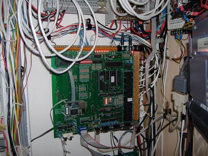
You can just see on the far right the bottom of a small laptop which is only folded down and used for programming the controller.

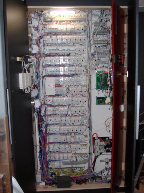
Then all the lights, doors, roller shutters, even the (magnetic) bathroom door locks are controlled by a large bank of control devices (apologies, but the camera really didn't do a very good job on this one) :
All this lot, and some more, is hidden behind the false back of a large cupboard (the back is itself a pair of doors that open to reveal this).

There is a LOT of star wiring here :rolleyes:

If you were still wanting to fully automate, then there are products to do it. I'd suggest you'd want to consider where you could locate multiple, smaller load switching panels to reduce the amount of cabling required. Whilst there are products to allow individual switching of circuits at the point of load (eg "smart" light switches etc), the cost soon racks up.
 
Back in the late 1980's an engineering aquaintance of mine built a "house for the future" with full automation controlled by two state of the ark PCs. He was really proud of it. But it was an ongoing project to get it working as he and his partner needed it to work. Not until they actually lived in it did they fully understand the difference between what they wanted to have and what they needed to have.

He never admitted it but it seems life under automation didn't work as intended and apparently after about 4 years he ripped out all the automation and replaced it with normal wiring.

My cottage will have some automation of the lighting primarily to allow ELV wiring in small cables ( 12 volt ) to the switches to remove the need to run mains rated 1 mm twin and earth in 490 year old wattle and daub walls.
 

DIYnot Local

Staff member

If you need to find a tradesperson to get your job done, please try our local search below, or if you are doing it yourself you can find suppliers local to you.

Select the supplier or trade you require, enter your location to begin your search.


Are you a trade or supplier? You can create your listing free at DIYnot Local

 
Sponsored Links
Back
Top