

I strongly recall that the common electricity meters were affected by the power factor ( phase angle between current and voltage ) and with mechanical meters the electicity companies required that the power factor was as close to unity as possible. An example of this was a large officle block in London where the escalators were kept running day and night even when the building was closed. The power factor of the motors cancelled out the power factor of the majority of the flourescent lighting ,.I also recall chart recordors used to record difference in phase angle as proof that the consumer ( large company ) was maintaining a power factor close to unity and thus not making the meter read less than was being used.
( To save me typing I have copied this from Wikipedia )
Electromechanical meters
The most common type of electricity meter is the electromechanical induction watt-hour meter.[14][15]
The electromechanical induction meter operates by counting the revolutions of a non-magnetic, but electrically conductive, metal disc which is made to rotate at a speed proportional to the power passing through the meter. The number of revolutions is thus proportional to the energy usage. The voltage coil consumes a small and relatively constant amount of power, typically around 2 watts which is not registered on the meter. The current coil similarly consumes a small amount of power in proportion to the square of the current flowing through it, typically up to a couple of watts at full load, which is registered on the meter.
The disc is acted upon by two sets of coils, which form, in effect, a two phase induction motor. One coil is connected in such a way that it produces a magnetic flux in proportion to the voltage and the other produces a magnetic flux in proportion to the current. The field of the voltage coil is delayed by 90 degrees, due to the coil's inductive nature, and calibrated using a lag coil.[16] This produces eddy currents in the disc and the effect is such that a force is exerted on the disc in proportion to the product of the instantaneous current, voltage and phase angle (power factor) between them. A permanent magnet acts as an eddy current brake, exerting an opposing force proportional to the speed of rotation of the disc. The equilibrium between these two opposing forces results in the disc rotating at a speed proportional to the power or rate of energy usage. The disc drives a register mechanism which counts revolutions, much like the odometer in a car, in order to render a measurement of the total energy used.
The type of meter described above is used on a single-phase AC supply. Different phase configurations use additional voltage and current coils.
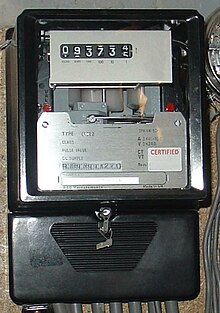
Three-phase electromechanical induction meter, metering 100 A 240/415 V supply. Horizontal aluminum rotor disc is visible in center of meter
The disc is supported by a spindle which has a worm gear which drives the register. The register is a series of dials which record the amount of energy used. The dials may be of the cyclometer type, an odometer-like display that is easy to read where for each dial a single digit is shown through a window in the face of the meter, or of the pointer type where a pointer indicates each digit. With the dial pointer type, adjacent pointers generally rotate in opposite directions due to the gearing mechanism.
The amount of energy represented by one revolution of the disc is denoted by the symbol Kh which is given in units of watt-hours per revolution. The value 7.2 is commonly seen. Using the value of Kh one can determine their power consumption at any given time by timing the disc with a stopwatch.
P = 3600 ⋅ K h t {\displaystyle P={{3600\cdot Kh} \over t}}
 .
.
( To save me typing I have copied this from Wikipedia )
Electromechanical meters
The most common type of electricity meter is the electromechanical induction watt-hour meter.[14][15]
The electromechanical induction meter operates by counting the revolutions of a non-magnetic, but electrically conductive, metal disc which is made to rotate at a speed proportional to the power passing through the meter. The number of revolutions is thus proportional to the energy usage. The voltage coil consumes a small and relatively constant amount of power, typically around 2 watts which is not registered on the meter. The current coil similarly consumes a small amount of power in proportion to the square of the current flowing through it, typically up to a couple of watts at full load, which is registered on the meter.
The disc is acted upon by two sets of coils, which form, in effect, a two phase induction motor. One coil is connected in such a way that it produces a magnetic flux in proportion to the voltage and the other produces a magnetic flux in proportion to the current. The field of the voltage coil is delayed by 90 degrees, due to the coil's inductive nature, and calibrated using a lag coil.[16] This produces eddy currents in the disc and the effect is such that a force is exerted on the disc in proportion to the product of the instantaneous current, voltage and phase angle (power factor) between them. A permanent magnet acts as an eddy current brake, exerting an opposing force proportional to the speed of rotation of the disc. The equilibrium between these two opposing forces results in the disc rotating at a speed proportional to the power or rate of energy usage. The disc drives a register mechanism which counts revolutions, much like the odometer in a car, in order to render a measurement of the total energy used.
The type of meter described above is used on a single-phase AC supply. Different phase configurations use additional voltage and current coils.

Three-phase electromechanical induction meter, metering 100 A 240/415 V supply. Horizontal aluminum rotor disc is visible in center of meter
The disc is supported by a spindle which has a worm gear which drives the register. The register is a series of dials which record the amount of energy used. The dials may be of the cyclometer type, an odometer-like display that is easy to read where for each dial a single digit is shown through a window in the face of the meter, or of the pointer type where a pointer indicates each digit. With the dial pointer type, adjacent pointers generally rotate in opposite directions due to the gearing mechanism.
The amount of energy represented by one revolution of the disc is denoted by the symbol Kh which is given in units of watt-hours per revolution. The value 7.2 is commonly seen. Using the value of Kh one can determine their power consumption at any given time by timing the disc with a stopwatch.
P = 3600 ⋅ K h t {\displaystyle P={{3600\cdot Kh} \over t}}