Notwithstanding BAS's points (most of which are valid), I think that you proposal is conceptually reasonable, and certainly a good/adequate basis for your up-front discussions with the electrician who will be involved.
John, thanks for the general comment. Equally, while I accept the validity of BAS’s points, I have tried to explain the reasons for asking for ‘advice’ as suggested in the title of this thread from the outset. While somewhat tangential to this thread, the following quote from the article link is somewhat reflective of my situation:
http://www.govyou.co.uk/part-p-of-the-building-regulations-scrapped/
"However there are other issues as well from a non-qualified but intelligent sensible DIYer. My daughter has a 50′s house with botched electrics from previous owners. We have had qualified electricians look at it and they say they can’t put right or improve obvious faults and can only rewire the whole house. My daughter is very poor and can’t afford the astronomical quotes and required disruption. The result is I repair the dangerous elements (e.g wires that were joined with insulation tape etc) probably to part P standard but certainly to a much safer level. As far as I’m concerned my first priority is to make it safe, regulations or not."
Your electrician will undoubtedly have views on details of your proposal. In particular, (s)he may well feel that all your proposed cable sizes represent 'overkill' - not just the 6mm² cable for hob and oven circuits that we've already discussed, but also the 6mm² for sockets circuit and 1.5mm² for the lighting circuit.
I did take onboard your previous advice about cable size. I also read up a little on ring versus radial circuits and compared the price of 6mm versus 4mm cable. Overall, I thought a radial design might be more sensible in this case, requiring the larger cable size indicated, and the cost difference between 4-6mm appears to only be a few £’s. However, there may be good reasons not to 'overkill' on the cable sizes.
(S)he will probably also have views on the optimum ways to distribute the circuits between the two RCDs in the new CU.
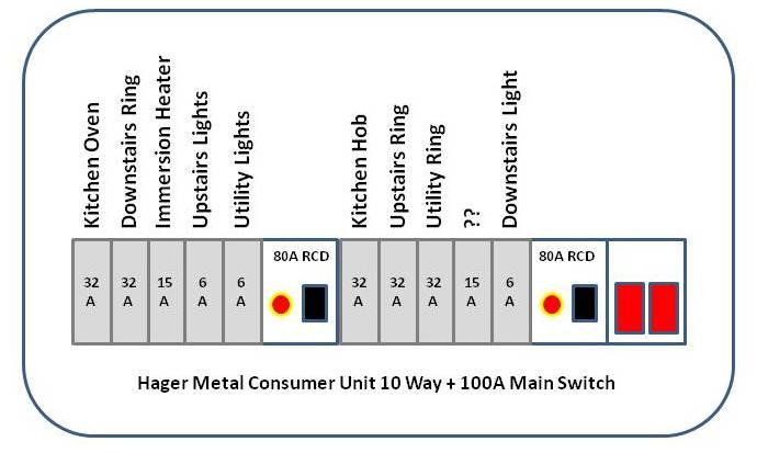
Based on early advice on this matter, I tried to balance the loading between the 2 RCD’s as being suggested by the attached diagram. Again, this is only a proposal for discussion not a statement of intent.
BAS's suggestion that enough spare cable be utilised so that the definitive connections to the new CU can be made without the need for joins in JBs is a good one.
Agreed. Truly I am listening to this advice and it is much appreciated.