Fan controller - got me stumped!!

Joined
17 May 2006
Messages
242
Reaction score
0
Location
Glasgow
Country
United Kingdom
Hi all

A friend just moved into a house where outside the bathroom there is a light switch (1 way) and a contactor controller for the fan - unfortunatlly all the cables were removed so having a problem sussing out how this was done.....

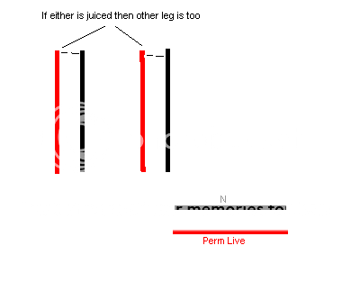
The wiring into the backbox:

If one leg of each of the top pair is powered up the other becomes live so seem connected straight through
Other set is a permanent live and neutral
wiring.png


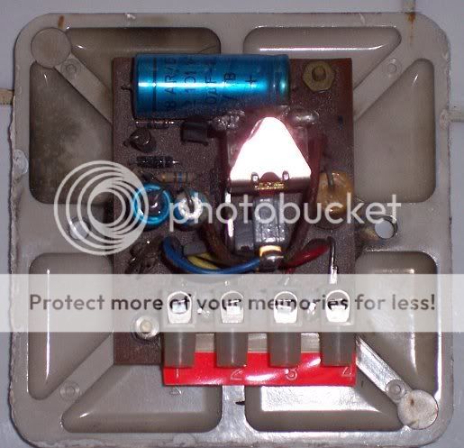
The switch they were connected into:
Appears to be a contactor and timer possibly
switch.jpg


I haven't opened the fan to see the connection inside but may have too - unless someone can suss out how it may have been wired...got me stumped :(

Any ideas welcome or if you need more detail etc lmk...bit of a long shot maybe!

Cheers
 
Sponsored Links
GaryMo said:
No contactor in there.

The metal triangular shape is some sort of switch that is pulled shut when power applied as far as I can see.....
 
My approach would be to connect all three neutrals together in a choc bloc to start with.

240 Volts will appear on the neutrals via either the lamp filament or fan motor if they are left floating. :eek: very dangerous. :eek:

Looking at your picture, there appear to be some soot stains on the back of the switch plate, suggesting something may have been fried, thus prompting it's disconnection.

Considering the timer switch in your picture, the four connections needed for it to work would be:-
a live feed in to power both outputs and the timer circuit,
an output from the switch to the light,
a timed output via the relay to the fan,
and a neutral to complete the power circuit to the timer.

but there's no way of knowing which one is which without the manufacturers instructions. Transposing any of the connections would almost certainly destroy the timer, if that hasn't happened already.

You may be able to replace the switch/timer with an ordinary 1 way switch, but you will lose the fan run-on facility. Connect live feed in to com, and both fan and light lives to L1, all three neutrals together in a piece of choc bloc, and all three CPCs together in the switch back box.
 
Sponsored Links
Thanks for that.....
I think the switch is goosed - looks like the floating cables touched it at some point.

Of course - forgot the neutrals will have 240!! doh! Wasn't thinking there!

One thing - none of them appeared to be a switch wire to the light......
 
the_jinj said:
GaryMo said:
No contactor in there.

The metal triangular shape is some sort of switch that is pulled shut when power applied as far as I can see.....

The triangle will be pulled down to the coil under it and this makes it operate the micro switch to which the blue wire is soldered.

But what energises the coil I cannot say ( Because I don't know )

But the black and coppery coloured debris suggests the copper tracks on the PCB have been vaporised which suggests it is probably beyond repair
 

DIYnot Local

Staff member

If you need to find a tradesperson to get your job done, please try our local search below, or if you are doing it yourself you can find suppliers local to you.

Select the supplier or trade you require, enter your location to begin your search.


Are you a trade or supplier? You can create your listing free at DIYnot Local

 
Back
Top