
- Joined
- 5 Oct 2009
- Messages
- 1
- Reaction score
- 0
- Country

Hi All,
Have tried to answer this from other posts but still not sure.
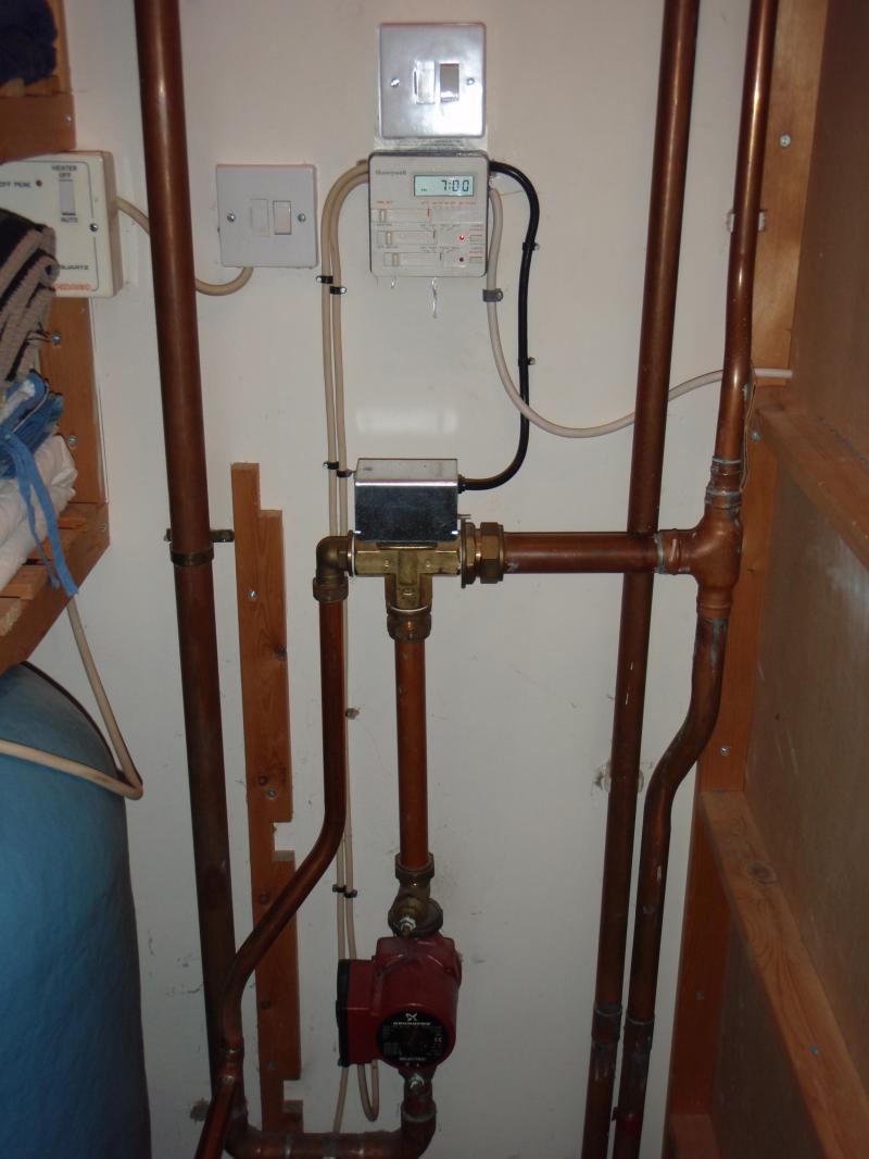
I had a heating and water system run by a program timer, which is a Honeywell item. (See diagram).
It used to have three wires coming out of the timer. The two white ones on the left went to the red and black pump and the hot water cylinder. The black one on the right goes to the three way valve. It used to run either hot water or heating individually or together. Today I added a Danfoss RMT230 room thermastat. On advice from a local plumber who has worked on the system, via phone conversation, I took a Neutral from the timer to the neutral on the RMT (4); I took a live from the heating side of the timer (which was originally connected to a white wire running to the valve inside the black casing) and connected it to the common input of the RMT (1); I then took the switched output from the RMT (2) and ran this to the original white wire going to the valve (inside the black casing).
When I first tested the system it seemed to work fine. Very pleased with myself. Then I tried to demonstrate it to the wife when she got home. "look what I've done honey". Didn't work. The only difference was that the water was already on this time.
Since writing this I have tried it different ways and now it seems to be working again.
Any thoughts on the way I have wired it? Have I got some basic logic wrong?
Hope the above explanation is clear'ish. Any help gratefully received. (Even though it seems to be working at the moment?)
Thanks,
Mike.[/img]
Have tried to answer this from other posts but still not sure.
I had a heating and water system run by a program timer, which is a Honeywell item. (See diagram).
It used to have three wires coming out of the timer. The two white ones on the left went to the red and black pump and the hot water cylinder. The black one on the right goes to the three way valve. It used to run either hot water or heating individually or together. Today I added a Danfoss RMT230 room thermastat. On advice from a local plumber who has worked on the system, via phone conversation, I took a Neutral from the timer to the neutral on the RMT (4); I took a live from the heating side of the timer (which was originally connected to a white wire running to the valve inside the black casing) and connected it to the common input of the RMT (1); I then took the switched output from the RMT (2) and ran this to the original white wire going to the valve (inside the black casing).
When I first tested the system it seemed to work fine. Very pleased with myself. Then I tried to demonstrate it to the wife when she got home. "look what I've done honey". Didn't work. The only difference was that the water was already on this time.
Since writing this I have tried it different ways and now it seems to be working again.
Any thoughts on the way I have wired it? Have I got some basic logic wrong?
Hope the above explanation is clear'ish. Any help gratefully received. (Even though it seems to be working at the moment?)
Thanks,
Mike.[/img]