

OK, I think I'm gradually getting unconfused. To be frank, I'd actually forgotten that there had been an 'earlier equation'. Just to be clear, everything I've done and written in the last couple of days has related to the 'second' equation, per your message #58OK sorry let me rephrase, the earlier equation I was trying to derive was simply what the difference between Ir and If in any given situation with *constant* voltage. That we indeed found the regs always asked for a better Rf. Then once I was clear on that I worked out the ratio of Ze to Ro to give the 0.94 voltage drop and plugged that in to the equation to derive the graph. However that kind of got lost in the noise as we were still clarifying the first equation.
Fair enough, but I'm not too sure how you could have thought that. What did you think the different rows in my tabulated simulations were - they were each for a different supply voltage (ranging from 122V to 238V in my first simulation), achieved by varying Ro.When you first posted your simulation I thought you were also simulating the constant voltage situation too, so sorry for not pointing it out explicitly that I was doing that.
Returning to the 'second' equation, it's easy enough to modify that so that Ir really is the PFC determined per the regs' method, but that creates a practical problem ...
Since the transformer voltage (Vt) terms no longer cancel, we are stuck with a Vt term in the final expression, and we will not normally (if ever!) know the value of that. All one can do (and I will try) is to explore the effect of varying Vt, with Ro constrained to values which result in supply voltages between 216.2 and 253V. I suspect that that constraint will seriously limit the range of transformer voltages that can be sensibly considered (i.e. without invoking ridiculous load currents). There is also now going to be a practical issue in relation to presenting this graphically (without having dozens of graphs), since we now have 5 variables to consider (Vt, Vs, Ze, Rf and 'error') - it was bad enough with the 4 variables I presented graphically yesterday, so I need to think how best to do this! Watch this space.
Very true, but I suspect that geography could present a problem. If it's any consolation, I've consumed a good few glasses of wine whilst partaking in this discussion, and there are probably more to be drunk before it's finished!!Anyway hope that makes sense. Far better to discuss this kind of thing over a pint anyway...
Kind Regards, John
") Excellent graphs.
Excellent graphs.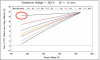
")

