Glow worm 70ff ultimate wiring??

Joined
8 Jul 2008
Messages
22
Reaction score
0
Country
United Kingdom
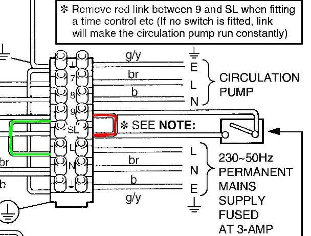
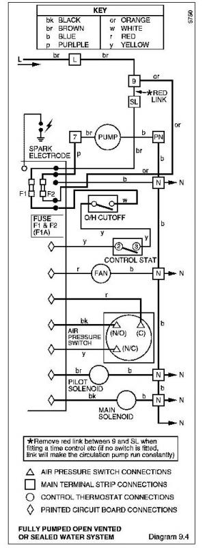
Can anyone help, still having problem with my boiler, pump runs non stop, boiler comes on any time day or night, i have rewired the entire system checked the 2 x 2 way valves all seems okay, i guess its a boiler problem, i have L,N,E wired to the pemanent live terminals, Pump supply to pump live, and wire from the thermostat, valves etc to SL, everything works but pump never stops, glow worm told me that the switch wire should be to terminal 9 and not SL i have tried this but the boiler will not start i dont think this is right as terminal 9 has a link wire to the permanent live, i have checked the boiler terminals with a multimeter and with power off there is a circiut between the live in terminal and the pump live, i am guessing that the thermostat in the boiler might have packed up as both of these wires go back to the thermostat.
Any ideas

Rob
 
Sponsored Links
go to your wiring centre/ double patress where heating wires are situated. turn clock to off on h/w and heating and check whether you are gettinqg 24o volts on orange wires.
 
Hi
Thanks for the reply, turned both water and CH off and got 240v between Orange wires and N

Rob
 
with the external controls set to off is the orange neon under the boiler still on if it is then you require a new pcb
 
Sponsored Links
Hi
Thanks for the reply, turned both water and CH off and got 240v between Orange wires and N

Rob

if you have 240v on the orange with the programmer off , its either a faulty zone valve or your wiring is wrong
 
Hi
Tried that turned the controls to off and the boiler neon is still on, looks like a new PCB how much do they normally cost?? with the HW and CH off and the orange wires at 240v is this not a fault with the valves i put my meter across grey and orange and this live and across brown and orange is not live, not sure how they work.

Rob
 
I have a Danfoss Heatplan 2 x 2 port vale wiring system, the 2 way valves are wired as follows TERMINAL 1 , live from mains, both grey wires, and boiler permanent live. TERMINAL 4 wire from programmer 4, wire 1 from room stat, TERMINAL 5 Brown from heating valve, wire 2 from room stat. TERMINAL 6 wire from programmer 3, 1com from cyl stat, TERMINAL 8 brown from HW valve, 2 call from cyl stat, TERMINAL 9 both orange wires, boiler SL. TERMINAL 10 pump live, boiler pump supply.
orange wires are always live even with HW and CH off at programmer.
 
Hi
Thanks for the reply.

My wiring is as follows (Danfoss Heatplan 2 x 2 port valves)

10 WAY CONNECTOR BLOCK

TERM 1 Live mains feed, 2 x Grey, Boiler Permanent live
TEMR 2 Neutrals
TERM 3 Earths
TERM 4 Programmer CH wire, Wire1 Room stat
TERM 5 CH Valve Brown, Wire 2 Room Stat
TERM 6 Programmer HW wire, 1com Cyl stat.
TERM 7 Neutrals link
TERM 8 HW Brown wire, 2call cyl stat
TERM 9 Both orange wires, Boiler SL (Goes to boiler SL connection)
Term 10 Pump live, Boiler Pump supply


Orange wires alway live even with CH and HW turned off at programmer
please help it has got me pulling my hair out, and i havent much left LOL

Rob
 
Your wiring is correct, so we need to look elsewhere.

Orange wires alway live even with CH and HW turned off at programmer
1 Is there a link between the SL terminal and terminal 9 on the boiler? If so, remove it. Then check the voltage on the oranges with CH and HW OFF - should be 0v. Check boiler operation - if OK, problem solved. Go to 5.

2 If it is 240v, remove the boiler SL connect from terminal 9 on the wiring centre and check voltage on the oranges when programmer is HW and CH OFF; If 0v, go to 3; if 240v, go to 4.

3 If 0v, then you are getting back-feed from the SL terminal on the boiler. Disconnect the SL wire from the SL terminal on the boiler and check the voltages on the boiler's SL and 9 terminals. One should read 0v, the other 240v. Connect the SL wire from the wiring centre to the one which measures 0V. Check boiler operation; if OK, problem solved. Go to 5.

4 If 240v, then the problem lies in one of the motorized valves. Disconnect one of the oranges and check the voltage on that disconnected wire - should be 0v - if 240v, the switch in the valve is welded together. If 0v, disconnect the other orange and test that one.

Remove actuator from faulty valve and inspect the internal switch. You may be able to separate and clean the contacts, otherwise it's a new actuator. Replace new/repaired actuator and check system; if OK, problem solved. Go to 5.

5 Job done. Go to pub. ;)
 
Hi
Thanks for your help , i disconnected both orange wires also disconnected the SL, 1 x orange 240v other orange about 95v sounds like they are both playing up, also on the boiler connector block i checked between the live feed in and the purple pump wire and there is a connection between them looks like the boiler thermostat has had it aswell as the are both connected to the thermostat. does this sound right??
 
i disconnected both orange wires also disconnected the SL, 1 x orange 240v other orange about 95v sounds like they are both playing up,
Did you do the checks in the sequence I gave. It was designed to help identify the cause of the problem.

on the boiler connector block i checked between the live feed in and the purple pump wire and there is a connection between them
It was the Switched Live (SL) terminal I was talking about. You found the Green Wire in the pic below; that should be there. It's the Red Wire which should not be there.


looks like the boiler thermostat has had it as well as the are both connected to the thermostat. does this sound right??
Do you mean the thermostat on the boiler (Control stat on the wiring diagram below) or the room thermostat?


DIYnot Local

Staff member

If you need to find a tradesperson to get your job done, please try our local search below, or if you are doing it yourself you can find suppliers local to you.

Select the supplier or trade you require, enter your location to begin your search.


Are you a trade or supplier? You can create your listing free at DIYnot Local

 
Sponsored Links
Back
Top