Guidance note 8 help...

Joined
13 Mar 2010
Messages
620
Reaction score
16
Location
London
Country
United Kingdom
Guidance note 8 - Section 5 Protective equipotential bonding

Im getting a bit lost here.....
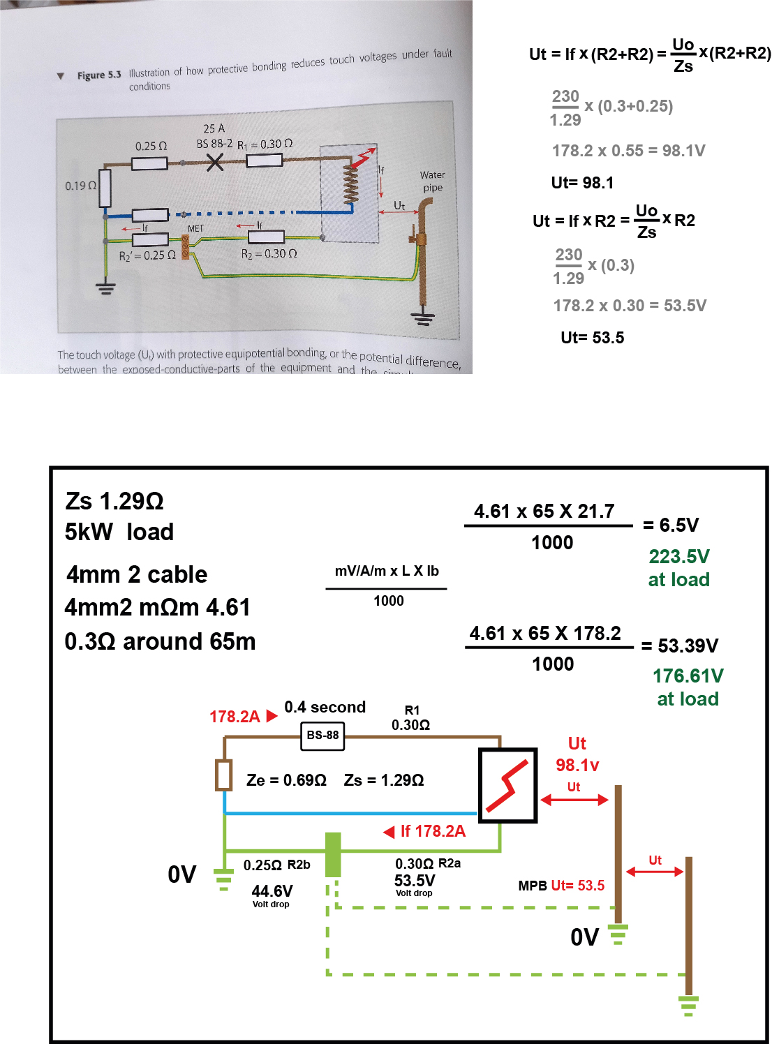
I have attached an image from the book, and my own version of the same image.... This section is about touch voltage and how that changes, if you add Protective equipotential bonding.

The basic premise is that, without bonding the touch voltage would be 98.1V, and with bonding it would be 53.5 V

So without bonding you are calculating the R2 of the CPC and the R2 of the means of earthing.
In this case 0.30Ω and 0.25Ω

With Bonding you are only calculating the CPC 0.30Ω

It seems to suggest that the impedance of the earthing conductor is no longer counted, as we have a additional 0V connection via the water pipe??

Im getting a bit lost here. A potential difference is between 2 point, so what voltage is the Exposed conductive part, and what voltage is the Extraneous conductive part.

Also It is seems to be saying the voltage dropped is the voltage that is appearing on the exposed and extraneous conductive parts as touch voltage.

But I understand voltage drop to be voltage 'lost' by the impedance of the circuit. So if you had a volt drop of 98.1 V you would have a voltage of 131.9V.

Any help in understanding this would be appreciated. Thanks

(I have guesstimated the cable size going of the R1+R2 readings)

 
Last edited:
Sponsored Links
MPB Touch voltage.jpg
 
Last edited:
I've been waiting for JohnW2 to reply. ... ... Until he does, perhaps you could read this thread detailing his realisations/discoveries about supplementary bonding. ... I can't believe it was as long ago. ....
Hi. I've been very busy, and have only just seen this, and it's far too late for me to try to respond now - but I'll try to find some time tomorrow (no promises, since my 'being busy' continues!).

In the meantime, my first observation is that that diagram from the book seems awful, and is probably going to take me some time to work out - having two "R2"s with different values (and a calculation including "R2+R2", when I suppose they are two different things!!) certainly doesn't help!

Kind Regards, John
 
Sponsored Links
Have looked and thought (in the light of day), I really can't understand that diagram from GN8, and I don't have a copy of that publication. Maybe someone can explain it to me but, if not, I think I may have to simply explain, 'from scratch', my way of looking at main bonding.

Kind Regards, John
 
The picture from the book is showing the earth fault loop path. The Zs is 1.29Ω The Ze being 0.69Ω. There is an earth fault on a resistive load (5kW) Which is sending a fault current down the CPC (0.30Ω) and down the means of earthing (0.25Ω) The figures next to the photo are the equations from the book which give the touch voltage (Ut) when no bonding is in place (98.1v) and the Touch voltage when it is ( 53.5Ω) The equations from the book seem to suggest that the means of earthing resistance (0.25Ω) is not needed in the equation when bonding is connected. I presume because a lower resistance earth path has been added
20220224_160430.jpg
20220224_160440.jpg
 
The picture from the book is showing the earth fault loop path. The Zs is 1.29Ω The Ze being 0.69Ω.....
OK, thanks - I'll read all that and see if I can make sense of it (but I may need to ask more questions!). I'm going to be tied up or the next hour or two, but will hopefully be able to say at least something after that. Watch this space!

Kind Regards, John
 
The picture from the book is showing the earth fault loop path. The Zs is 1.29Ω The Ze being 0.69Ω. There is an earth fault on a resistive load (5kW) Which is sending a fault current down the CPC (0.30Ω) and down the means of earthing (0.25Ω) The figures next to the photo are the equations from the book which give the touch voltage (Ut) when no bonding is in place (98.1v) and the Touch voltage when it is ( 53.5Ω)
OK, I'm still thinking about this, but a few preliminary comments:

1... I still think that the diagram in the book is awful. Without the text which you have now posted, I really couldn't make much sense of it at all!

2... The 5kW load is pretty irrelevant, the only effect it has being the relatively small reduction in supply voltage at the exposed-c-p, resultant from VD due to the load current (and see ** below).

3... I'm still trying understand exactly what they are suggesting but, at first sight, they seem to be assuming that the extraneous-c-p (water pipe) represents a zero impedance path to earth, which clearly will not be the case in practice. They are perhaps trying to present a hypothetical 'worst case' but, in the real world, if the path to earth has a finite impedance, then the 'touch voltage' (with bonding) will be appreciably less than their calculations would suggest (since potential of the extraneous-c-p will, under fault conditions, rise to appreciably above true earth potential).

[ ** their figures don't seem very realistic. With a supply-side RL (hence presumably also RN) of 0.25Ω, even if the final circuit had a zero RL+RN, the supply voltage of the entire installation would fall by about 20V if one turned on a ~10kW shower, which I don't think is our usual experience ]

Edit: I would add that :

1... the 0.19Ω they include in the fault loop, which seems to be the 'internal impedance' of the source, rather confuses things, and I may be inclined to ignore that for my initial calculations.

2... it is not really realistic to have R1=R2 (=0.30Ω) for the within-installation wiring since, other than for 1mm² lighting circuits, R2 will always be greater than R1. However, I will initially go with their (unrealistic) figures.


More soon.

Kind Regards, John
 
Last edited:
OK, first for the 'no bonding' situation ...

It is only because of their ('confusing') 0.19Ω 'internal resistance of source' that they get the touch voltage (without bonding) of 98.1V. If one ignores that 0.19Ω, then, on the basis of their (probably unrealistic for TN-S) assumption that the impedances of the L and E components of the 'external parts of the loop are equal (=0.25Ω) and their (definitely unrealistic, other than for 1mm lighting circuits) assumption that R1=R2 (=0.30Ω) within the installation, the 'touch voltage (potential of the exposed-c-p above true earth, the potential of the extraneous-c-p when no current was flowing through it) would be exactly half of the supply voltage, namely 115V. [note that I am, at least for now, ignoring the 5kW load]

In practice, that touch voltage would be greater than 115V because, for nearly all circuits R2 is greater than R1.

Kind Regards, John
 
Right, now to the 'with bonding' situation ... .

For any given assumptions regarding the "R1 and R2" both in the supply network (i.e. "Ze") and within the installation (Zs minus Ze), the touch voltage only depends on two things, the impedance of path to earth from the extraneous-c-p and the impedance of the bonding conductor - ironically two things which the calculations in GN8 do not appear to have considered !!

Again ignoring the 'confusing' "0.19Ω" and the (essentially irrelevant) 5kW load in GN8, if I've got it right the diagram below shows what the fault loop boils down to and how the calculations work out. Although it looks complicated, I've done my best to make it clear, and the maths is really extremely simple, even if it doesn't look as if it is - however, please just shout if you need help in understanding my scribblings!

The 'box' at the bottom of my diagram explains the 'limiting condition' which one approaches as the impedance of the extraneous-c-p to earth becomes increasingly large relative to the impedance of the earth component of the Ze. Following that are three graphs, showing this graphically (the first for extraneous-c-p impedances to earth up to 2Ω . the second up to 10Ω, and the third up to 50Ω.

Moving back to the without bonding situation, the very bottom 'box' in my diagram re-asserts that, without bonding, and using the (probably unrealistic) GN8 assumptions, the 'touch voltage would be 115 V -although, as I said, in practice more than 115 V, since R2 will nearly always be higher than R1.

Assuming I've got this all right, the bottom line therefore seems to be that, using GN8s (probably unrealistic) assumptions about R1 and R2 in the network and installation, main bonding will appreciably reduce touch voltage appreciably, down from 115+ V to a minimum of about 62.7 V (closer to {but never below} that figure as impedance {to earth} of the extraneous-c-p increases), but much less reduction in touch voltage if the impedance of the extraneous-c-p (to earth) is very low - say if it is much below about 0.5Ω.

I hope that makes sense and is all roughly correct. However, what I haven't yet had time to do is to look at GN8's calculations to see why they differ a bit from mine (their "0.19Ω", and maybe the 5kW load may well have a lot to do with it!).

Questions on a postcard :)

upload_2022-2-25_3-37-47.png


upload_2022-2-25_3-40-27.png


upload_2022-2-25_3-41-4.png


upload_2022-2-25_3-41-24.png


Kind Regards, John
 
It might be worth pointing out for non-electricians reading this that the situation described only applies during a fault in the very short time until the fuse or circuit breaker disconnects the supply.

However, what I haven't yet had time to do is to look at GN8's calculations to see why they differ a bit from mine (their "0.19Ω", and maybe the 5kW load may well have a lot to do with it!).
Hasn't GN8 just totally misrepresented (misunderstood?) the situation by merely considering the Volt-drop on the various conductors due to the fault current - as if a person were touching one of those conductors at two points; albeit exposed-c-p and MET - while completely ignoring the fact that the main bonding conductor is also earthed at its connection to the pipe (extraneous-c-p) thus introducing the various other current paths?
 
It might be worth pointing out for non-electricians reading this that the situation described only applies during a fault in the very short time until the fuse or circuit breaker disconnects the supply.
True, provided that the fault current is (as we usually assume) high enough for it to be "a very short time" before a protective device remedies the situation. However, in the event of a fault of less than 'negligible impedance', hence lower fault current, there can be an 'appreciable' touch voltage for an 'appreciable' period of time before the fuse/breaker operates. For example, using the GN8 figures, with NO main bonding, a 100A fault current would presumably result in a 'touch voltage' of 55V.
Hasn't GN8 just totally misrepresented (misunderstood?) the situation by merely considering the Volt-drop on the various conductors due to the fault current - as if a person were touching one of those conductors at two points; albeit exposed-c-p and MET - while completely ignoring the fact that the main bonding conductor is also earthed at its connection to the pipe (extraneous-c-p) thus introducing the various other current paths?
As I said, I've yet to try to work out what they have done. However, given that they appeared to have ignored the two main things which determine touch voltage (per my graphs), I don't have a lot of confidence that they've done it particularly correctly! I hope to get around to looking at this soon.

Kind Regards, John
 
As I said, I've yet to try to work out what they have done. However, given that they appeared to have ignored the two main things which determine touch voltage (per my graphs), I don't have a lot of confidence that they've done it particularly correctly! I hope to get around to looking at this soon.
I should have added ...

... I remain confused by, and 'suspicious of', the "0.19Ω" introduced in the GN8 calculation as some sort of "internal impedance" of the source. As I see it, Ze, as it would be measured, is Ze, regardless of anything.

Kind Regards, John
 
For example, using the GN8 figures, with NO main bonding, a 100A fault current would presumably result in a 'touch voltage' of 55V.
That would mean a person had to touch two points on a conductor between which the impedance was 0.55Ω.
That is not possible in the diagram as part of that 0.55Ω is the supply cabling.
 

DIYnot Local

Staff member

If you need to find a tradesperson to get your job done, please try our local search below, or if you are doing it yourself you can find suppliers local to you.

Select the supplier or trade you require, enter your location to begin your search.


Are you a trade or supplier? You can create your listing free at DIYnot Local

 
Sponsored Links
Back
Top