Hi Experts.
I have an issue which I’m hoping you can help with. Basically, I recently fitted a new alarm which went pretty smoothly. The next stage was to fix the external sounder, and that’s where i’m struggling a little.
I have:
• Risco NovaGard 6 External Sounder (with LED’s and Strobe)
• Visonic Powermax+ Alarm
The issue is just how I connect the wires between the 2 units. I’ve given it a go, but seem to be way off the mark, as not even the LED’s are flashing.
The powermax+ alarm panel guide can be found here (http://www.jclautomation.com/docs/73900ug.pdf) – page 6.
The External sounder is this one (http://www.sourcesecurity.com/docs/fullspec/Nova6-bro%29%5B1%5D.pdf) but that doesn’t contain the full info required, so I’ve typed out what’s in the paper manual:
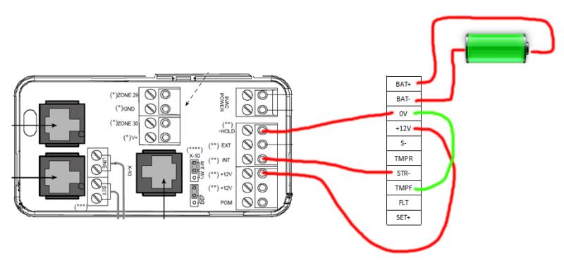
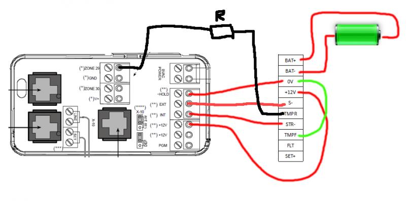
BAT+ (Connections for Ni-MH Battery)
BAT- Connections for Ni-MH Battery)
0V (The negative supply to this terminal should be permanent as it is the – hold off for the SAB/SCB function.)
+12V (The supply to this terminal is normally taken from the bell+ of the control panel (depending on manufacturer) and provides the + hold off for the SAB/SCB function)
S- (Negative trigger for the sounder. If JP1 is set for SAB, power for the sounder is derived from the 12V and0V terminals. If JP1 is set for SCB, power for the sounder is derived from the onboard battery. When used in serial mode this terminals will be used as a data input)
TMPR (Negative tamper return to the control panel. When used in serial mode this terminal will be used as a data input)
STR- (Negative trigger for the strobe light Power for the strobe is derived from the 12V IN & 0V IN terminals)
TMPF In standard mode (non NovActive) this terminal must always be linked to 0V)
FLT (Terminal will activate (0V low) in the event of a battery fault or low panel volts)
SET+ (A positive signal to this terminal will activate the setting confirmation sound. Note: for this feature to be enabled, the address jumper A3 must be in position)
I’m having to borrow some ladders to fit this, and so there’s no great rush to get it working, but i’m hoping (snow permitting) to wire it up at the weekend.
I’m sure it can’t be that difficult, but it really has me stumped! Any help would be much appreciated, and if there's some standard wire colors that I should adhere to, that would be cool too")
Many thanks,
Regards,
Dave.
I have an issue which I’m hoping you can help with. Basically, I recently fitted a new alarm which went pretty smoothly. The next stage was to fix the external sounder, and that’s where i’m struggling a little.
I have:
• Risco NovaGard 6 External Sounder (with LED’s and Strobe)
• Visonic Powermax+ Alarm
The issue is just how I connect the wires between the 2 units. I’ve given it a go, but seem to be way off the mark, as not even the LED’s are flashing.
The powermax+ alarm panel guide can be found here (http://www.jclautomation.com/docs/73900ug.pdf) – page 6.
The External sounder is this one (http://www.sourcesecurity.com/docs/fullspec/Nova6-bro%29%5B1%5D.pdf) but that doesn’t contain the full info required, so I’ve typed out what’s in the paper manual:
BAT+ (Connections for Ni-MH Battery)
BAT- Connections for Ni-MH Battery)
0V (The negative supply to this terminal should be permanent as it is the – hold off for the SAB/SCB function.)
+12V (The supply to this terminal is normally taken from the bell+ of the control panel (depending on manufacturer) and provides the + hold off for the SAB/SCB function)
S- (Negative trigger for the sounder. If JP1 is set for SAB, power for the sounder is derived from the 12V and0V terminals. If JP1 is set for SCB, power for the sounder is derived from the onboard battery. When used in serial mode this terminals will be used as a data input)
TMPR (Negative tamper return to the control panel. When used in serial mode this terminal will be used as a data input)
STR- (Negative trigger for the strobe light Power for the strobe is derived from the 12V IN & 0V IN terminals)
TMPF In standard mode (non NovActive) this terminal must always be linked to 0V)
FLT (Terminal will activate (0V low) in the event of a battery fault or low panel volts)
SET+ (A positive signal to this terminal will activate the setting confirmation sound. Note: for this feature to be enabled, the address jumper A3 must be in position)
I’m having to borrow some ladders to fit this, and so there’s no great rush to get it working, but i’m hoping (snow permitting) to wire it up at the weekend.
I’m sure it can’t be that difficult, but it really has me stumped! Any help would be much appreciated, and if there's some standard wire colors that I should adhere to, that would be cool too
Many thanks,
Regards,
Dave.