
Help with Resideo TotalHome Thermostat relay wiring

Joined
28 Dec 2009
Messages
77
Reaction score
1
Location
Devon
Country
United Kingdom
Hi, I have an existing Honeywell CM927 thermostat that connects to a R6660D relay which in turn is connected to our Grant Vortex Pro combi oil boiler. The wiring looks like this currently:
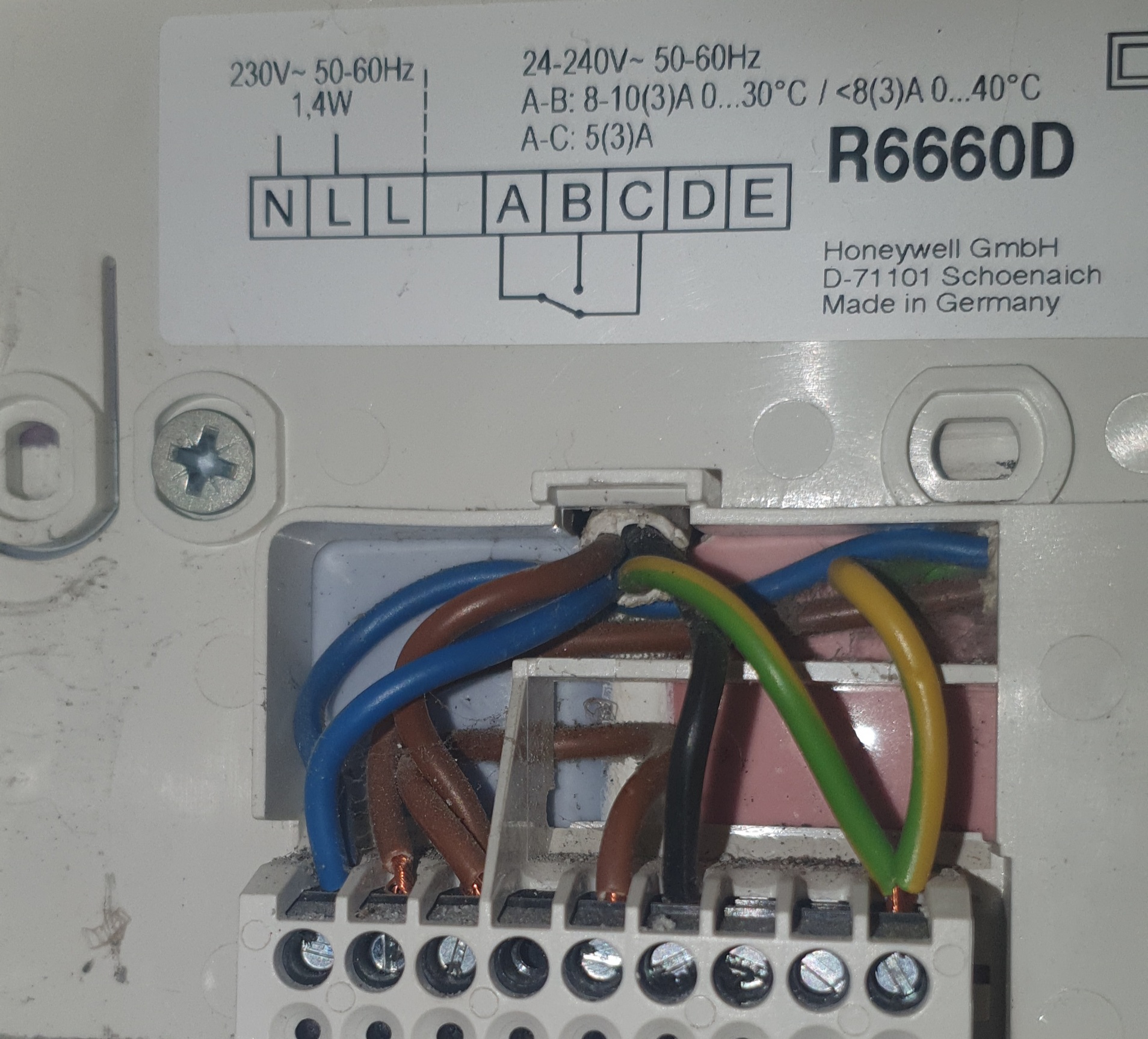
20261008_144825.jpg


where:

N – blue from mains and from boiler
L – brown from mains
L - brown from boiler and brown linked to A
A – brown coming from L above
B – black from boiler
C – unused
E – 2 × Earth

The new TotalHome TTHWFP relay has this diagram:
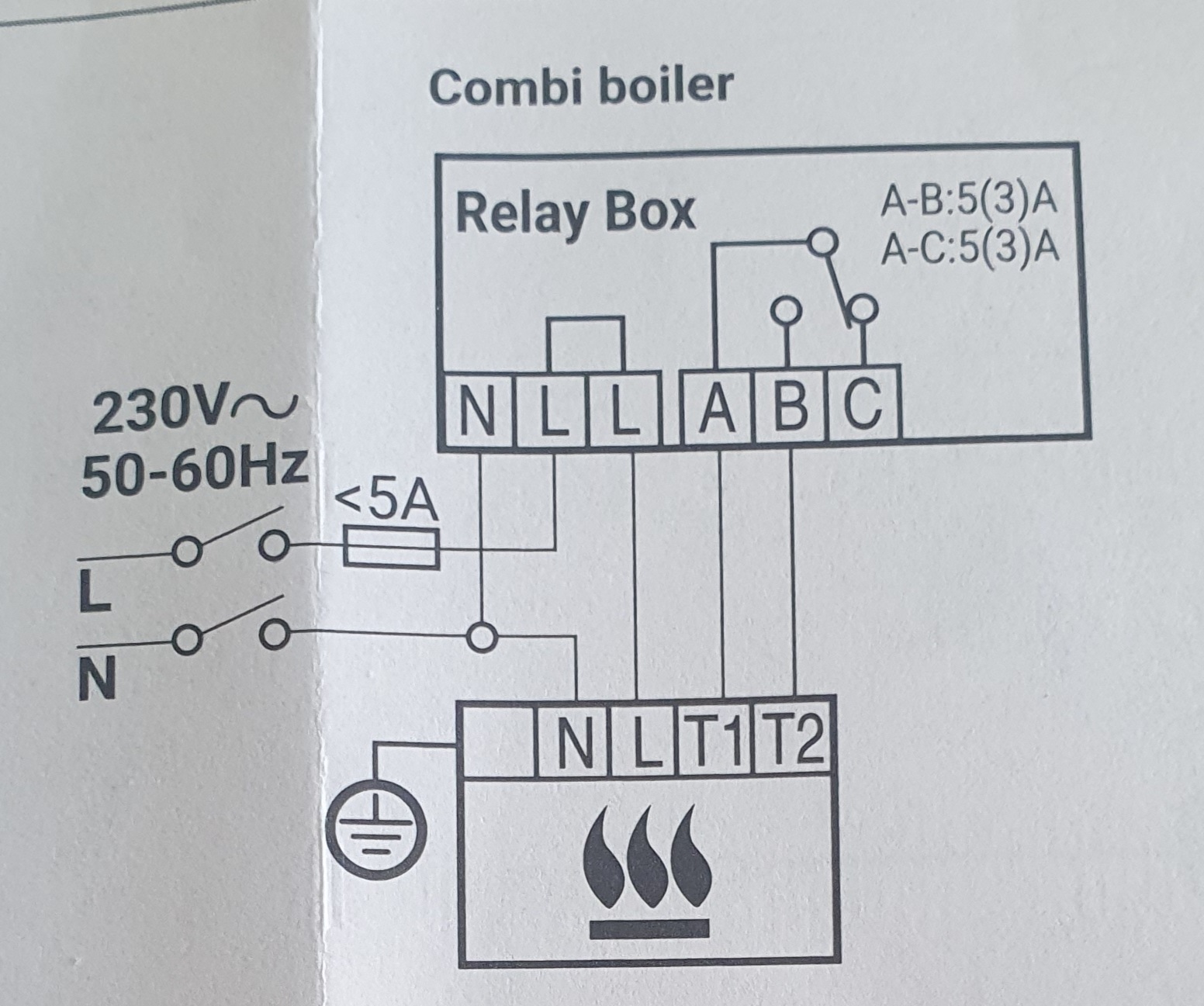
20261008_144805.jpg


So I think it should be:

N - blue from mains and from boiler
L – brown from mains + brown, with L linked to adjacent L
L - brown from boiler

Is that bit correct so far? That leaves my single black cable from the boiler...into A with B and C unused? I know there is no earth connection so those two existing cables will have to be connected to each other using a wago or terminal block.

Thanks

Dan
 
The wiring is are exactly the same for both units as per their respective diagrams:

N= Neutral (Blue wires from mains supply and to boiler)
L= Permanent Live (Brown wires from mains supply and to boiler)
A= Common - insert link between it and L
B= Normally Open (Black wire to boiler)

You don't need a link between the two L terminals they are already connected together inside the Relay Box for you.....

Screenshot 2026-10-09 092726.jpg


.....so effectively they are the same terminal. Use the L on the left for the brown wires from the mains supply and to boiler, and the L on the right for the link to A
 
Thanks so much Stem. I always double-check my understanding :), what you're saying in a visual sense is this:

20261008_144805-colour.jpg


where I will use a wago to join the existing earth cables.

The other end boiler-side terminals look like this:

20261009_100913.jpg


That doesn't change anything does it?

Thanks

Dan
 
In a visual sense no, that is not how the black wire would be. It'd follow the diagram line. You shouldn't be touching that at the boiler side anyway though, as mentioned you can wire it up exactly the same as before
 
Diagram looks correct to me. Except the link between L and A would be outside the relay box not inside it. But I guess that's artistic licence :)

Nothing changes at the boiler end. You are simply installing a relay box that has the same functions and connections as the one it's replacing.
 
In a visual sense no, that is not how the black wire would be. It'd follow the diagram line. You shouldn't be touching that at the boiler side anyway though, as mentioned you can wire it up exactly the same as before
Thanks, so black does not go into B...or is it wrong because I naively drew it back to T1 on the diagram? Thanks, Dan
 
Thanks, so black does not go into B...or is it wrong because I naively drew it back to T1 on the diagram? Thanks, Dan
Yep, the latter. The way you've drawn it the boiler would run constantly. You'd have to adjust boiler wiring to mess that up though!
 
Yep, the latter. The way you've drawn it the boiler would run constantly. You'd have to adjust boiler wiring to mess that up though!
Thanks, yes, I just wanted to show the black switched live heating wire going to the boiler so was a bit careless...I can't afford to run the boiler constant, especially at current oil rates!! :D
 
I think you will need the link. I have never known them to come with Honeywell/resideo ones
 

If you need to find a tradesperson to get your job done, please try our local search below, or if you are doing it yourself you can find suppliers local to you.

Select the supplier or trade you require, enter your location to begin your search.


Are you a trade or supplier? You can create your listing free at DIYnot Local

 
Back
Top