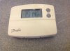
Yours appears quite an easy installation and shouldn't be to difficult to swap over because the Danfoss is already a programmable thermostat which combines time and temperature control, so there isn't any time control built into the boiler to remove or disable. From your photo the thermostat looks like a Danfoss TP5001.
My system already has a wireless thermostat.
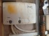
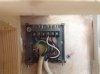
As it is a wireless thermostat, it is an RF variant and the control wires should be terminated at a Danfoss RX1 receiver (see picture below). If your receiver is an RX1, then you can proceed as below.
Danfoss TP5001 wireless thermostat and RX1 receiver

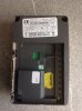
I found that I had only 4 wires on the old system
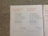
With 4 wires at the receiver, the wiring terminals used should be as below. However, if yours is different, or your thermostat is not a TP5001 RF with a RX1 receiver, don't proceed and post back with details of what you do have. The RX1 terminals allow the four wires to be identified as follows:
Danfoss RX1 Receiver
Terminal N = Permanent Neutral wire
Terminal L = Permanent Live wire
Terminal 2 = Common wire
Terminal 3 = Heating 'on' wire
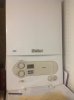
As you have a combi boiler, you require the
Hive single channel receiver, to replace the Danfoss RX1 receiver. The wires should be reconnected to the corresponding Hive terminals that have exactly the same functions as the Danfoss ie:
Hive Single Channel
Permanent Neutral wire = N terminal
Permanent Live wire = L terminal
Common wire = Terminal 1
Heating 'on' wire = Terminal 3
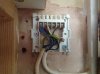
I found that I had only 4 wires on the old system and on the new hive I need 5.
I'm not sure why you think you need 5 wires for the Hive though. If you are referring to a separate earth wire, the Hive does not need an earth connection, but there is a tether to park it if one is present.
Note of caution: Some installers will use a green / yellow wire as one of the circuit conductors and not an earth. If you have a green / yellow wire going to one of the RX1 receiver terminals listed above, it is not an earth.