Honeywell 6360B Thermostat

Joined
27 Aug 2022
Messages
6
Reaction score
2
Country
United Kingdom
Hi,
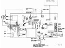
I've a Honeywell 6360B attached to a Heatline Combi - I've manuals for both but am struggling.
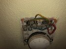
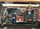
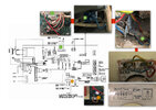
The Heatline is set to use low voltage for thermostat (the 230v thermo connector is jumped) and I can see the two 'switch wires' exiting from the 24v thermo connector but lose sight of them as they disappear behind tiling with the mains supply (there's an isolation switch as few feet away). Across the house at the Honeywell there's a four core cable live/neutral/yellow/bare earth - which is wired to terminals 1/2/3 & earth.

Everything works fine, I just want to add a more modern thermostat (L/N & low volt switch) - but I'm struggling to understand how it's working now since my reading from the Honeywell circuit is the yellow cable is a switched neutral @ 230v. Is it possible there's more going on somewhere - extra resistance or something.

Thanks.
 

Attachments

  • ch_box.jpeg
    ch_box.jpeg
    206.8 KB · Views: 75
  • ch_wires.jpeg
    ch_wires.jpeg
    235.8 KB · Views: 63
  • signal-2022-08-26-160622_002.jpeg
    signal-2022-08-26-160622_002.jpeg
    295.8 KB · Views: 68
Sponsored Links
I can’t see the RT connection on the pcb, but if everything works as is, and you’re measuring 230vac on the Honeywell, then I would say it’s mains switching.
 
This is the board diagram - I don't have a reliable meter, but mains tester driver isn't lighting on the thermostat connections in any state. It's definitely controlling the boiler properly though.
 

Attachments

  • board.jpg
    board.jpg
    283.7 KB · Views: 51
  • Thanks
Reactions: CBW
It needs testing properly, and the brown link that’s in could be controlling the heating as opposed to the room thermostat. Simple test would be put the heating on, leave room stat on low and see if it kicks in, ensuring the boiler thermostat on the front is high.
 
Sponsored Links
The compensation resistor in the old thermostat will not work with an extra low voltage supply, but some times that is a good point not bad, it means the difference between switch on and switch off temperatures is greater, but it will still work with extra low voltage.

Be careful with the phrase "low voltage" in USA it means what we call extra low voltage, the ISO say low voltage AC is between 50 - 1000 volt, but the Americans don't seem to take any notice of that, and call 12 volt low voltage, and since Americans seem to behave in a daft way, many manufacturers use American terminology instead of international standards origination terminology, they think the British are clever enough to work out what they mean.

Best option is to use a battery powered thermostat, hard wired are are loads, but wifi seems only Nest e is battery powered.

I don't like Nest e as it will not work with TRV's, but it may suit you.

I do agree you need to test, but the boiler manual does say "While the boiler's main pcb, pump, three-way valve and gas valve are supplied at 230V AC., all other components and associated circuits are supplied at low voltage." Which I am sure should say "While the boiler's main pcb, pump, three-way valve and gas valve are supplied at 230V AC., all other components and associated circuits are supplied at extra low voltage."
 
Is it possible this is a 'slave' unit and there's another box hidden away or bypassed somewhere - I'm perplexed by how it is working OK now - give or take a degree or two maybe. I can hear it click in when the room temp is passed.
We have two boilers on separate circuits/supply (once was two houses) the other had no thermostat so I added a new smart/wireless with new wiring, can do similar with this as need to sync the two 'houses' via app etc - but I don't like the idea of dead wiring, particularly as I don't know what it's connected to.
 
You're right on the extra/low voltage - in their defence I posted a grab from an online manual as the printed one is minging
 

Attachments

  • signal-2022-08-28-114540_002.jpeg
    signal-2022-08-28-114540_002.jpeg
    327.5 KB · Views: 39
Last edited:
So I've traced the RT which goes from the low-voltage on board to a scotch block at the side of boiler connected to a 'L/N' of a supply cable.

Then behind the isolator/switch I can see that cable connected via another scotch block to yellow/red cable (can't see the rest of their cable, but I assume it's the other end of the cable connected to the thermostat.

I've tried to put it all in one image...

Why is this working and not killing the board?
 

Attachments

  • bg.jpg
    bg.jpg
    279.2 KB · Views: 55
Last edited:
Just in case anyone happens upon this later and since most instructions/videos have a different config - after testing with a meter this was wired as follows:
Pin 1 (red in photos) and Pin 3 (yellow in photos) were connected to the' low voltage' thermostat terminal on the boiler (~15VAC) and Pin 2 (blue wire) was connected to neutral on the load side of the isolator switch (earth was connected likewise to the isolator).
Still not 100% on why this actually worked, but it did - I was able to re-use the cabling albeit wired simply to supply a modern smart thermostat with 230VAC and run a volt free connection back to the boiler (all jumpers etc being the same).
 
  • Thanks
Reactions: CBW
What seems evident to me, and why it would work is, the RT connections on both sides of the board are suitable for 24v or 230 vac.
 

DIYnot Local

Staff member

If you need to find a tradesperson to get your job done, please try our local search below, or if you are doing it yourself you can find suppliers local to you.

Select the supplier or trade you require, enter your location to begin your search.


Are you a trade or supplier? You can create your listing free at DIYnot Local

 
Sponsored Links
Back
Top