Honeywell Evohome BDR91relay wiring help

kts

Joined
27 Jul 2014
Messages
7
Reaction score
0
Location
Sussex
Country
United Kingdom
Hi all

I thought I had this sussed but then got myslef confused when trying to wire in the relay next to the wiring centre.

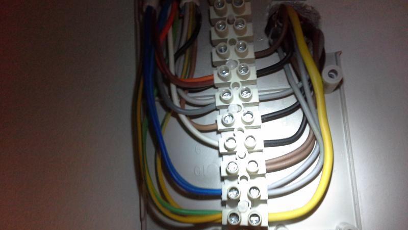
This is what it currently look likes:

(Sorry the pic is upside down)

The wires that you can see coming in at the top left of the picture. From left to right is the pump, mid position valve and cylinder stat.

Having read various posts before but never started one, i know you guys like to know the system set up so this is it:
The boiler is an ideal icos he12, vented cylinder with a Drayton hts3 t/stat, Drayton ma1 mid position valve

Does anyone know which wires I need to pick up on here please to go into the bdr91?

Thanks
 
Thanks for your response.

I should have mentioned that i have a 3 wire honeywell room tstat in the hall and there is also a Drayton lp241 2 channel programmer in the kitchen downstairs which i know i will have to leave this set the CH on constant for this to work (I do want to get rid of this eventually when I add another bdr91 and the cyl tstat for the system then I can do away with the programmer altogether, or thats what I'm hoping for.

Well from what I figured out for the valve.

Position 9 in the wiring centre is the white wire, on the otherside I think this connects to a black wire. Which I think is the room t/stat call wire.

Position 7 is the grey wire which I think feeds the cyl stat as a satisfied call and also goes to the programmer as HW Off.

Position 6 orange which I think connects to the cylinder stat calling and is a black wire, the pump live wire which his brown and the boiler live which is black.

Position 11 blue which I think connects to the room t/stat which is grey and also connects to the boiler, pump and programmer all as neutral.

This is the point I started to get confused as I need a live, neutral or common I think and a switched live or can the switch live be bridged by connecting the L to to b in the relay?
 
You need to determine which are the thermostat wires.

The input TO the thermostat will be replaced by the input to A on the receiver.
The output FROM the thermostat will be replaced by the output from B on the receiver.
The third wire will, presumably, be a neutral which should be disconnected.

Also, the receiver will require permanent Live to L and Neutral to N.
Terminate the CPC (earth wire) safely if there is nowhere to park it.

The timer will need to be set to CH permanently ON.
 
Hi, thanks.

That's the problem though.

I do not know which wires from the wiring centre go to the thermostat or whether the thermostat wires go straight to the boiler.

I was going to temporarily remove the old thermostat so it didn't interfere with anything and eventually use these wires downstairs to provide power to the wall unit for the evotouch so didn't want to disconnect these altogether from the wiring centre (assuming they go there) but was hoping for help from the forum to identify the equivlents to put the relay next to the wiring centre (as this will remain neater as it is in the airing cupboard as I know I could put the relay where the room tStat is and replace that but as mentiojed plan to use live, neutral and earth to power the wall charging mount.
 
The white valve wire is CH on, so connect this to the relay B terminal.

Terminal A can either be connected to live or the timer CHon.

Personally I would leave the exusting Tstat connected for now (in parallel) and set it to 5 degs.

It could be useful when your wireless batteries go flat!
 
Why not ?

That assumes the motorised value is directly connected into that junction box.
and given the presence of an orange, grey and white wires, I would say it was.
 
Thanks.

Seems like I have opened up a can of worms!

Not sure if it makes a difference but the house was new 6years ago so not sure if there are any set formats for wiring that need to be followed for regs at this point that wouldnhelp what wires are which in the wiring centre?

If it makes any difference the black wire at the room tstat is switched, brown is common/live, grey is neutral and then there is a earth wire so not sure if you tell from the piccie if this is wired back to the centre or noting andyprk comments if white from valve is CH on and this is connected to a single black wire, then would it make sense that this would be a switch wire (Black) for the room tstat?
 
Follow up.....

As per my opening post - mid position valve goes stright into the wiring centre.
 
Why not ?
Because we do not know how it is wired.
There may be a standard wiring method but it is not the only way to do it.


That assumes the motorised value is directly connected into that junction box.
Yes but that doesn't say where the thermostat wires go.

and given the presence of an orange, grey and white wires, I would say it was.
I agree but that doesn't say where the thermostat wires go.
 
If it makes any difference the black wire at the room tstat is switched, brown is common/live, grey is neutral and then there is a earth wire so not sure if you tell from the piccie if this is wired back to the centre or noting andyprk comments if white from valve is CH on and this is connected to a single black wire, then would it make sense that this would be a switch wire (Black) for the room tstat?
It may well be.

You are doing as I said and determining where the thermostat wires go.
 

If you need to find a tradesperson to get your job done, please try our local search below, or if you are doing it yourself you can find suppliers local to you.

Select the supplier or trade you require, enter your location to begin your search.


Are you a trade or supplier? You can create your listing free at DIYnot Local

 
Back
Top