• Looking for a smarter way to manage your heating this winter? We’ve been testing the new Aqara Radiator Thermostat W600 to see how quiet, accurate and easy it is to use around the home. Click here read our review.

How to attach new loft floor joists to existing wall plate/rafters

Joined
2 Dec 2004
Messages
648
Reaction score
5
Country
United Kingdom
Hi.

I am boarding my loft for storage.

The existing ceiling joists are small and only able to support ceiling load. I therefore need to build a new timber floor over the top of the existing ceiling.

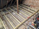
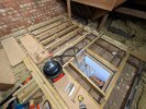
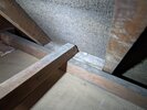
I have already completed two sections, where I was able to utilize existing brick internal supporting walls to rest new joists on. I attach two photos of completed sections.

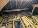
My third and final section is more tricky as I need to span across to the outer wall of the house as there are no other solid walls I can use.

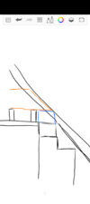
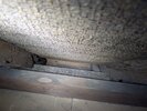
My issue is how to rest new 7x2 joists onto the existing wall plate, when the existing rafters at a 45 degree roof angle limit the available bearing for the new joists. I attach a photo showing the final section I want to board.

If I cut the new joists at 45 degrees I will compromise the bearing end substantially.

I'm happy to include some extra pictures or diagrams if it helps explain the problem I need to solve, please let me know what you would like to see.

Thanks.
 

Attachments

  • PXL_20250607_161813164.MP.jpg
    PXL_20250607_161813164.MP.jpg
    498.5 KB · Views: 96
  • PXL_20250614_150105521.jpg
    PXL_20250614_150105521.jpg
    449.5 KB · Views: 76
  • PXL_20250614_180818918.jpg
    PXL_20250614_180818918.jpg
    379.5 KB · Views: 73
If I cut the new joists at 45 degrees I will compromise the bearing end substantially.
Not enough to cause a problem. Your rafters are much smaller and have a birds mouth notched into them "compromising the bearing" and the roof hasn't failed. You also have to remember that the majority of the load these joists carry, bears on the end nearest the camera, because the far end isn't usable space, unless you're planning on storing your hundreds of rolls of lead sheeting there

You already have one such timber cut thus and it's helped support your entire ceiling for years:
1749971310906.png


Cut your new ones to match the roof pitch and slide them out so they're just shy of touching the felt. All will be fine, and they will have plenty of bearing
 
Not enough to cause a problem. Your rafters are much smaller and have a birds mouth notched into them "compromising the bearing" and the roof hasn't failed. You also have to remember that the majority of the load these joists carry, bears on the end nearest the camera, because the far end isn't usable space, unless you're planning on storing your hundreds of rolls of lead sheeting there

You already have one such timber cut thus and it's helped support your entire ceiling for years:
View attachment 384353


Cut your new ones to match the roof pitch and slide them out so they're just shy of touching the felt. All will be fine, and they will have plenty of bearing

Thanks for the reply.

That piece of timber is just a tie which is tie-ing all the ceiling joist together, it's not taking any vertical load. They have however added an additional block onto the wall plate to raise it up to sit that timber on. The joist you can see in the foreground is just a ceiling joist running parallel to the wall, that's not the wall plate. The actual wall plate is behind that and lower.

If I add a block to pack the wall plate up, and slide the joist over it, I will have about 100mm of bearing but it will be right at the point where it's cut as shown in my sketch. Is that sufficient strength at the end?

What about bolting a metal triangular plate at the end of the joist to strengthen the end, or also bolting it to the rafter or strengthening the rafter?
 

Attachments

  • Screenshot_20250615-094602.png
    Screenshot_20250615-094602.png
    142.3 KB · Views: 37
Close up of corner and looking down to the wall plate itself.
 

Attachments

  • PXL_20250615_100740260.jpg
    PXL_20250615_100740260.jpg
    415.9 KB · Views: 41
  • PXL_20250615_100748473.jpg
    PXL_20250615_100748473.jpg
    310.3 KB · Views: 41
Oh, yeah, it'll be fine. If you're still concerned set yourself up and experiment; cut one end to 45 degrees and put two blocks on your driveway the distance apart of the span when installed in the loft, put another couple of joists either side and a board over the top for stability, then load it up with 5x the load it will have when in service, huge stack of bricks, half a car etc. the load should be at the same place it will be when live (ie not at the sloped end because the head height there isnt big enough to admit it)

I'll PayPal you a fiver if it fails

You can bolt and glue it to the rafter if it makes you feel better; I don't think it will be necessary for strength but it's a reasonable shout to keep it in place
 
Last edited:
@robinbanks thanks again for the advice. I did the approach above, cutting 45 degrees and resting them on blocks sat on top of the wall plate. It seems to be ok, obviously time will tell but as you say there isn't much weight on it.

In another section of the loft I would like to span a new beam approx 3m from wall plate to wall plate. But, I won't be able to get a full size beam in in one piece.

Can I join a beam halfway along by overlapping it and bolting it together, like this:

image.png
 
Yes; the strength comes from the length of the overlapping section. The longer you can make that the better. Glue between and bolt through, will give a very solid result.

Don't forget there are other ways to get long beams into awkward places in lofts, e.g whipping a tile off..
..and you can make strong beams out of multiple layers of shorter sections with joints that do not coincide
e.g if you had 18mm ply in 200mm strips that are eg 2m and 1m long then arranging them glued and bolted in a stack where you have 2m+1m then the next layer is 1m+2m alternating then you have all the joints sandwiched between solid wood either side and you'd generate a beam 3m long, 200mm deep and 6 layers (100 wide) (and you'd install it so the 200 was the vertical)

Some impressively huge wooden beams can be made by bonding multiple thin layers together - google LVL, glulam or parallam - made in a factory the leafs are very thin, glued and formed in a roller press in continuous fashion for incredible lengths. Made DIY you'd use glued/bolted sections of thinner sheet, themselves made of very thin sections..

1753166064888.png


Kinda like a kitchen worktop is made of vary small blocks all glued together so the joints don't align, or a brick wall has vertical joints that are always spanned by solid brick above and below (glulam is like a brick wall the blocks have horizontal glue planes, parallam / LVL have vertical glue planes)
 
Last edited:
@robinbanks thanks.

Ive cleared the area of insulation now so I can see what I have to work with.

I'll try and explain but it might be easier with a diagram.

This area of the loft is above a bedroom with a large bay window. The bay window is a flat roof protrusion from the house. It is supported, I believe, by wooden beams spanning the 2.6m opening from the brick work outer walls either side.

Above the beam is a triangular gable wall, which is the wall in the picture below in the loft.

image.png


So the beam spanning the bay window in the room below supports this brick gable end, which in turn supports roof purlins and the roof ridge.

The ceiling joists run parallel to this, from wall plate to wall plate either side of the space, so they aren't connected to this gable at all.

My proposal is to bolt a ledger beam to this gable, and then run new joists from here perpendicular back to the main loft area which Ive already framed out and boarded.


Here is the bedroom below. The gable wall in question is supported above this bay window.

PXL-20250126-150114071.jpg


My main concern is that I don't know for sure what is supporting this gable end brickwork. It must be a fairly substantial beam, as the bay window opening in the room below is 2.6m wide and its double brick thick. Ive seen other 7x3 beams in the loft so it could be a double 7x3 beam supporting this end wall.
 
Last edited:
I managed to save head space in our loft by adding a second 4" joist [literally] on top of the existing ones! We used C24 timber, and the two joists had to be connected every 600mm with steel fixing plates.
Building Regs were happy and there was zero flex in the floor.
 
Thanks for the reply.

That piece of timber is just a tie which is tie-ing all the ceiling joist together, it's not taking any vertical load. They have however added an additional block onto the wall plate to raise it up to sit that timber on. The joist you can see in the foreground is just a ceiling joist running parallel to the wall, that's not the wall plate. The actual wall plate is behind that and lower.

If I add a block to pack the wall plate up, and slide the joist over it, I will have about 100mm of bearing but it will be right at the point where it's cut as shown in my sketch. Is that sufficient strength at the end?

What about bolting a metal triangular plate at the end of the joist to strengthen the end, or also bolting it to the rafter or strengthening the rafter?
Just sister the joist where it sits on the wall plate if you're worried. You've removed bearing area by cutting the joist on an angle to fit under the roof, so double or triple up the width to compensate.
 
Hi all, so I need to do a bit more to satisfy myself that the structure is going to be secure before I start this work.

What I have is a gable end wall that I need to attach the ledger beam to.

This gable end wall is sitting atop a structural beam which is spanning a bay window opening in the room below.

Here is a cross section diagram of the arrangement.

image.png


Im concerned that resin fixing onto this gable wall won't be structurally sufficient because its already supported on top of an opening.

@robinbanks would you have an opinion on this please? I can provide some more pictures if it helps.
 
So the new ledger beam carries the floor? It has its own stiffness, and it's fixed to something carried by an existing beam. The forces on the resin anchors are shear rather than pullout. I don't think there is anything to be concerned about; the existing structure demonstrably self supports. Fixing a ledger to it overall achieves a stiffer construction and the new ledger is sufficient to carry the new floor (consider how it would work if only the ends of the ledger were resin anchored or if it was simply supported; loads on the ledger would go down the walls to the founds; the bay window beam isn't being asked to carry anything extra. If the new ledger were anchored in the middle, the construction as a whole bears the new floor, but we already know the ledger alone is capable of carrying the floor and the beam carrying the opening)
 
So the new ledger beam carries the floor? It has its own stiffness, and it's fixed to something carried by an existing beam. The forces on the resin anchors are shear rather than pullout. I don't think there is anything to be concerned about; the existing structure demonstrably self supports. Fixing a ledger to it overall achieves a stiffer construction and the new ledger is sufficient to carry the new floor (consider how it would work if only the ends of the ledger were resin anchored or if it was simply supported; loads on the ledger would go down the walls to the founds; the bay window beam isn't being asked to carry anything extra. If the new ledger were anchored in the middle, the construction as a whole bears the new floor, but we already know the ledger alone is capable of carrying the floor and the beam carrying the opening)
Now that's what I call an answer!
 

If you need to find a tradesperson to get your job done, please try our local search below, or if you are doing it yourself you can find suppliers local to you.

Select the supplier or trade you require, enter your location to begin your search.


Are you a trade or supplier? You can create your listing free at DIYnot Local

 
Back
Top