How to read pump graph?

Joined
8 Nov 2016
Messages
37
Reaction score
0
Country
United Kingdom
Hi,


I've been looking for some info on how to correctly read pump graphs. Information seems to be a bit difficult to find.

Anybody with knowhow can give me some details how to read the following chart?
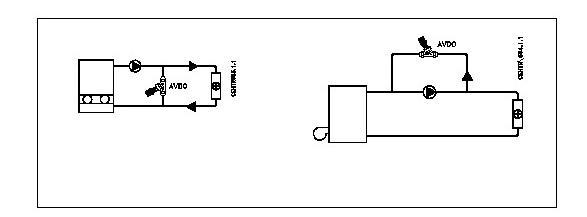
(Pump is fixed on stage 1 by setting d19)

The residual pump discharge height depending on the by-pass valve is shown in Fig. 3.10.1 (ecoTEC plus) and 3.10.2 (ecoTEC plus 637 / 837).


Screen Shot 2016-12-07 at 13.41.49.png


When running at 20 kW (Max, set on d0) the difference between flow and return is reported (d40/41) as 14 degrees. This translates to roughly 1220 litres of water heated (by 14 degrees) per hour. Correct?

So this is what the pump pushes around. Now how to interpret the graph.

Am I correct is saying that in that case the resistance of the system is around 150 mbar, or 1.5 meter of head?
 
Sponsored Links
20kW for 1 hour is 20,000 x 60 x60 = 72 MJ (Watts x seconds_in_1hr)
Water specific heat capacity is 4181 J/kgC (1l water = 1kg)
So 1 liter raised by 14C is 4181 x 14 = 58.534 kJ

72MJ / 58.534 kJ = 1230 l

So yes 1220 l is about right.

I would guess that is you are on the _ . _ . then that would be ~130mBar

But that assumes that you are putting in 20kW to the water. If it is a modulating boiler it might not be.
 
Am I correct is saying that in that case the resistance of the system is around 150 mbar, or 1.5 meter of head?

Possibly, but there are 4 different pump curves at 1220 l/h and no information to show which one applies. I'm sure you can work it out with the manual.

Assuming that is right, then that is the system resistance at that flow rate ONLY. The system curve is an equation
dP x (Kv)^2 = Q^2, where

dP is the pressure difference across the system/ pump pressure difference, Q is the flow rate Kv is a constant, the flow coefficient for that specific system.

The gist of that is that the system resistance is proportional to the square of the flow rate. You'd need 4 times as much pressure differential to get twice as much flow.

That value of Kv only applies to that system, if you have TRVs, they'll be moving around and constantly changing the value of Kv.
 
Last edited:
@Onetap

Yes there are 4 curves, that's part of my puzzle. I think because it is

a) a two speed pump. It is fixed at speed 1, as the graph indicates this would be the -.- line i believe.
the -- line would be the second speed.

b) there is an automatic bypass valve in the system too:

"The appliances have an adjustable by-pass valve.
The pressure can be adjusted between 170 and
350 mbar. Approx. 250 mbar is preset (mid-position). "

so that would be represented in the high, middle and lower graph lines?

(To be honest then I would expect there to be 3 lines for each pump speed, but maybe they overlap or are irrelevant?)

Problem is that there is no documentation in the manual which line is which, it's like it's assumed everybody would understand what the grey line means, and what the dotted line means...

Anybody a clue regarding these lines?

Waldo
 
Sponsored Links
The bit that gets me is Lift [mbar] for the vertical axis units. Lift is neasured as a distance and mbar are a measurement of pressure.

There is a relationship ..... 1 bar = 1000 mbar and 1 bar will lift water to a height of approx 10 metres at which height there will be no pressure left to create flow

That said when providing data on pumps intended for lifting water or fluids to a higher level the amount of "lift" is appropriate. But in a circulating pumped system lift is less relevent than pressure to over come resistance to flow around the system
 
The info is in the manual; you just have to hunt for it.

5.8 Adjusting the by-pass
The appliances have an adjustable by-pass valve.
The pressure can be adjusted between 170 and 350 mbar. Approx. 250 mbar is preset (mid-position).
The pressure changes by approx. 10 mbar each time the adjusting screw is rotated. By turning right, the pressure increases and turning left decreases it.


170, 250 and 350 correspond to the three horizontal lines on the graph. The -.-.- line is low speed and ---- is high speed. Although not shown, the low speed would still level off at the bypass valve setting - thy just do not bother to show it.

The boiler may be set to a max 20kW output, but that doesn't mean the boiler is producing this continually. Firstly it will depend on the output of your 8 rads. Assuming an average of 1.5kW per rad, that's a total of 12kW. The boiler will automatically reduce its output (modulate down) to produce 12kW, which is the lowest the boiler can modulate. So the flow rate (for a 14C differential) would be approx 740 litres/hr.

You can find the output of your rads using any online supplier's data (unless you have fancy designer rads) as there is only a few percent difference between manufacturers for the same size/type. I f you rads total less than 12kW it will be running in on/off mode all the time, so setting it to even 20kW will be too high.

If the boiler is switching on and off when there is still a call for heat (room not up to temperature), then the boiler is unable to modulate low enough. Best to check this on a very cold day as all boilers will run in on/off mode when the external temperature is higher than about 10C as the hating requirement will be half the calculated value.

Your boiler is, in all probability, oversized.

The fact that the bypass limits the pressure produced by the pump makes me think that it is not connected between flow and return but between pump input and output; as in the drawing on the right, below.

 
The bit that gets me is Lift [mbar] for the vertical axis units. Lift is measured as a distance and mbar are a measurement of pressure.
I saw that and couldn't believe it would appear in a manufacturer's installation manual. But then I read, in the same manual:

The residual pump discharge height depending on the by-pass valve is shown ...

What are they talking about? A pump for moving water from one level up to a higher level; or a circulator for sending water round a closed circuit?

I gave up at that point!
 
@D_Hailsham from what I can see about the pump and bypass (Vaillant ecotec 637) it's a bypass between flow and return as in diagram 1 you gave.

So would you say the following is correct:

With bypass at default settings, that would allow 1200 litres of water to be pumped around at diff. pressure of about 130/150 mbar.

If the flow through system is reduced (for whatever reason), this would increase diff. pressure and reduce flow until about 1000 litre/hr when the bypass would be opening and allowing a bit of water to flow through the bypass and maximise diff. pressure to it setting of 250 mbar?

And can you see from these graphs *how much* water would be going through?
 
Lift (discharge head) is a perfectly normal way to charactise any centrifugal pump, particularly one in a closed system - after all, the eye of the pump is a lower pressure, but is sat under a column of water too - the height of that column of water on the suction and discharge side of the pump is the same, so it cancels out. whether you have 1 metre or 10 metres or 100 metres overall height doesn't make a squat of difference, because however much pressure you think the pump is working against on the discharge side, it's equally helped out on the suction side by having that much "over pressure" on the eye on the impellor. So you're left with the difference in pressure/height and that's why it's expressed in metres head. It's just overcoming the resistance once the water is flowing through all the bends and valve seats etc. It's just how much pressure the centrifugal pump ADDS to whatever is on the suction side.

Look up the terms "pump run out" and "pump shut off" to give you an idea of what's happening at the extremes. The first is minimum pressure but maximum flow, the other is minimum (none) flow but maximum pressure.

Nozzle
 
OMG!!! The Google Warriors are having a Field Day!! Innate drivel!!

Here OP, have a Butchers at this video, it may make it clearer;

 
To who are you directing your remarks about google warrioring?

Nozzle
 
Last edited:

DIYnot Local

Staff member

If you need to find a tradesperson to get your job done, please try our local search below, or if you are doing it yourself you can find suppliers local to you.

Select the supplier or trade you require, enter your location to begin your search.


Are you a trade or supplier? You can create your listing free at DIYnot Local

 
Sponsored Links
Back
Top