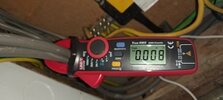
How would you clamp meter a ring main ??

Joined
15 Feb 2009
Messages
195
Reaction score
36
Location
Norfolkshire
Country
United Kingdom
I am asking how you would clamp a ring main as i just asked Refoss who make electrical monitors for electrical consumption, & asked how to monitor a ring main?, should i ct clamp 1 cable or both?. They come back with this.:

To monitor the total power consumption of the ring circuit, we recommend:
  1. Install one CT clamp separately on each of the two Live conductors
  2. Since the current can be distributed differently between the two sides depending on the location of the loads, the readings from the two CTs should be combined to obtain the total current/power consumption of the ring circuit.
  3. Then, you can use the merge channel function to combine the two CT channels and display the total data for the ring circuit.
Now its bad enough getting these CT clamps in any fuse board, but this board has 4 rings, so i dont think we will go down this route as we wont get 14 CT clamps in a 10 way board.
 
Can You get 10 of them in, then? I haven't actually ever used one, but if they can clamp round the two line wires going into an MCB, that would seem more practical.
 
Can You get 10 of them in, then? I haven't actually ever used one, but if they can clamp round the two line wires going into an MCB, that would seem more practical.
Tight, At the moment on this board it all MCB's & i was thinking of upgrading to RCBO's & might have a look for a larger board. I could also go down the route of fitting some 6x6 trunking & strip the cables back into the trunking & fit the CT's in the trunking. But it would be intresting to know if you would get different readings clamping 1 or 2 or 1&2 together.
 
I do see the problem, unless the CU is made by Refoss then the clamps need to be outside the board.

Seems unlikely the clamps have been used during the type testing.

I looked at clamping on my clamp meter, and there simply is not the room, so I clamped around the tails Diffrence line neutral 8 Feb 24 reduced.jpghere looking at earth leakage, and turned the RCBOs off one at a time, and with current used, the totals did not add up.

But the question has to be why? I note with the clamp for the iboost+ it gives a distance between it and any other clamp, which would simply not work with clamps inside the CU.

I was only doing it for general interest, if using them to charge for power used, then very different.
 
I do see the problem, unless the CU is made by Refoss then the clamps need to be outside the board.

Seems unlikely the clamps have been used during the type testing.

I looked at clamping on my clamp meter, and there simply is not the room, so I clamped around the tails View attachment 421440here looking at earth leakage, and turned the RCBOs off one at a time, and with current used, the totals did not add up.

But the question has to be why? I note with the clamp for the iboost+ it gives a distance between it and any other clamp, which would simply not work with clamps inside the CU.

I was only doing it for general interest, if using them to charge for power used, then very different.
I get the impression they have catered for the American market with the clamps they are using as the boards over there are very much like our old Crabtree boards that had lots of room. They also supply 16 x 40A ct's & 2 x 100A cts as a lot of American home have 220v. Not quite sure how this works with 230/415 vs 120/220 as i dont think the US has 3 phase in houses, its two lots of 120. ?
 
Think you have missed my point, in a DB yes you may be able to fit CT clamps, but in a CU no, as not type tested with CT clamps in the CU.

And second I have found CT clamps interfere with each other, and should not be close together, they will be too close together inside a consumer unit.

So it will need an adaptable box with the CT clamps in, they will not go in the CU.
 
Just put ONE CT round both (all*) legs of the ring. The magnetic field will just add and you don't need to do anything more.
* Some of our circuits have 3 or more as they also have a radial off the RCBO.
 
And second I have found CT clamps interfere with each other, and should not be close together, they will be too close together inside a consumer unit.
I could see clamps doing so if the ferrite faces not properly mated, better using fixed toroids as they are (manufacturing faults or damage excepted) a complete magnetic circuit with minimal leakage.

At a previous job, we had a client that built DBs for large commercial developments. Typically they put CTs on every circuit, using PCBs with two rows of CTs, staggered only a little to allow them to have the same pitch as the MCBs/RCBOs. Definitely close enough to interfere if that were a problem.
 
Seems that’s all you need to do

I did wonder initially but it’s not something I ever had
tothink about anyway although it’s done a lot checking leakage and they cancel mostly except for the difference
 
It make me wonder if these new switches/mcb's are the way to go & fit them in a separate plastic board after the RCBO board & have the advantage of consumption/meter, over/under volt & amps plus a time switch on each circuit, very handy for lighting circuits. I say plastic to help with wifi/zigbee. You would also get warning anywhere in the world of any problems at home. There are a few types about, but its the type below i was looking at. Only shame on these is no off/peak metering.
cbtimere.JPG
 
I can see the energy monitoring use rather than messy clamping

Seems only over-voltage protection not under , hmm

Remote control of circuits - No mostly and not a sound electrical practice

Overload etc. No. A dedicated DB should always do that
 
Last edited:

If you need to find a tradesperson to get your job done, please try our local search below, or if you are doing it yourself you can find suppliers local to you.

Select the supplier or trade you require, enter your location to begin your search.


Are you a trade or supplier? You can create your listing free at DIYnot Local

 
Back
Top