I-Beam Connections

Joined
24 Dec 2014
Messages
45
Reaction score
2
Location
Oxford
Country
United Kingdom
I have a few questions about how structural beams are connected for a project I'm doing. I have all the structural calculations, padstones, joints from a SE, I'm not putting the beams in myself - this is quite probably obvious to any decent builder, I'm just interested to understand - not least that I may perhaps be able to sensibly select a builder!

Part of my structure has a ring beam of UC supported at one end by tube (CHS). There's no detail on how it's joined. The bottom I'm guessing some sort of plate on the floor, but at the top the diameter of the CHS is pretty much the same to the beam it supports (88.9x4 mm CHS under a 152x89x16 UB). How are the two attached? Welded?

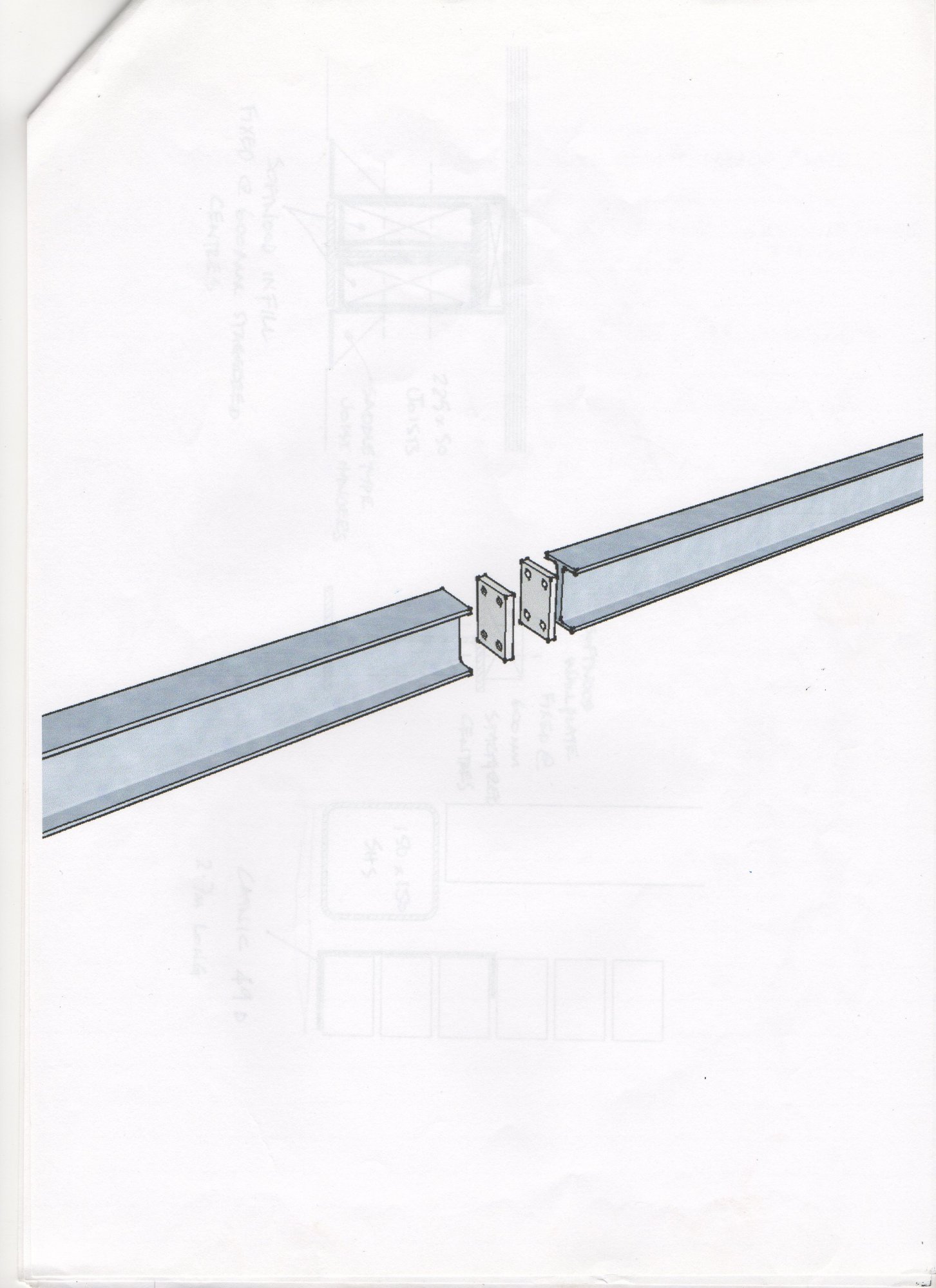
The other end of the beams are bolted to a bigger (203x203x71 UC) beam with cleats. The calculation picture (which has clearly come out of some software) shows the top of the beams flush, rather than the bottom being flush. I assume that this is just how the software prints it out and it's not important what height the cleats are bolted to on the bigger beam?

I had thought I was missing a joint bolting where two beams join at right-angles (the 203x203x71 UC and a separate 152x152x37 UC holding an upstairs wall) until I realised that of course the second is much shorter then the first. I'm assuming that the end of the 152UC can rest on top of the bottom flange of the 203UC?
 
Sponsored Links
All this should be specified by whoever designed the beams, as it may be important where abouts in the web holes are made and what size etc.
 
A structure is only as good as the connections between the individual parts, otherwise it becomes a mechanism.
Clearly your SE has not done the whole job.
 
I like that structure becoming mechanism comment. I bet that's a joke told at SE gatherings!
 
Sponsored Links
Oh, there's pages and pages of detail about other connections, and a blanket 'get the builder to call me if anything is unclear'; but having zero experience I'm merely trying to ascertain what might be normal and how dumb my questions are.
 
Usually, a bolted connection is made into the web - the incoming beam has a pate welded on the end, with 2 or 4 holes, and these are bolted through holes in the web of the receiving beam.
But the SE needs to specify the bolt spacings and size/type of bolt.
For small domestic loadings, you could sit one beam on top of the other, or sometimes even rest the incoming beam on the bottom flange of the main beam without bolting or welding; it works, but is not 'by the book'.
 
Hi,

It's not totally clear to me from the description what this all looks like but I can perhaps offer some general comments that might help.

The chs column would probably have a rectangular baseplate and capplate with the beam sitting on top. The actual geometry of the capplate depends on the space available around it. The alternative might be a vertical fin plate welded on the side or through the chs, but then you need to worry about the tube walls buckling so that's a determination for a pro based on the actual loads.

Beam to beam connections could be endplates, fin plates or loose angle cleats. I doubt very much that resting one beam on the other is a healthy option as that introduces bending across the flange as well as an unrestrained eccentricity that will induce twisting.

Sorry I can't be more specific. However this is really just minor stuff that the SE can get a design out of his software for in seconds. Best to let them give you some detailed connections as ultimately it's their PI insurance that underwrites the whole thing.

Regards
 
I doubt very much that resting one beam on the other is a healthy option as that introduces bending across the flange as well as an unrestrained eccentricity that will induce twisting.

It's true that any connection beam-to-beam which is not into the web of the main beam will induce torsion, but with domestic-scale loadings, it's not normally an issue.
 
I had this problem with a client/architect whereby I was practically begging for some steel design detail from the client. I didn't know whether it was the client being a skinflint or the architect being lazy, but I ended up doing the drawings myself.
I'll post my efforts later if anyone is interested.
 
It's true that any connection beam-to-beam which is not into the web of the main beam will induce torsion, but with domestic-scale loadings, it's not normally an issue.

The physics are the same, bad practice, but I guess that's why we apply load factors?
 

DIYnot Local

Staff member

If you need to find a tradesperson to get your job done, please try our local search below, or if you are doing it yourself you can find suppliers local to you.

Select the supplier or trade you require, enter your location to begin your search.


Are you a trade or supplier? You can create your listing free at DIYnot Local

 
Sponsored Links
Back
Top