Installing Pyrnoix belle and twin alert on scantronic 9752

Joined
16 Aug 2012
Messages
642
Reaction score
20
Location
London
Country
United Kingdom
Good Afternoon all,

I'm in the process of setting up a 9752 panel, all contacts/pir's/keypads/expanders etc wired up, but stuck on the bell boxes and internal sounders i got.

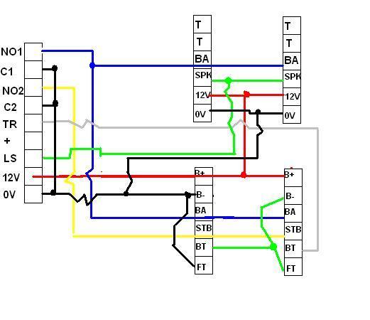
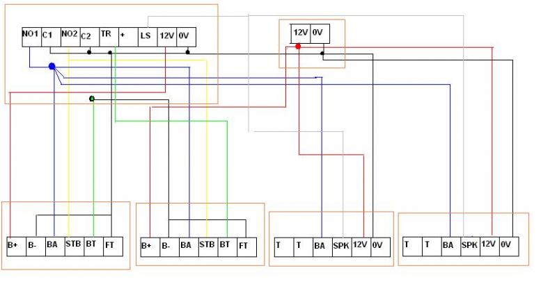
I'm looking to install two pyronix belle's as per the diagram provided in the installation manual - one set to SAB, one set to SCB,
Bell trigger sent to both, as is the strobe trigger,
TF from one feeds into the BT of the next, otherwise wiring as it would be for single bellbox.

Problem is that neither the belle or twin alert's connection details for scantronic matches up with the available connectors on the panel itself, and the scantronic manual doesn't give an example for any pyronix... (use to be there for the 9448 when i last installed one of them!)

not sure if i should post the connection details on the forum, is someone able to provide me with the connections as i need them? (either by email or private message?)

Also can i connect the tampers of both twin alerts in between the belle's? or is there somewhere else for me to connect the tamper on the panel? (cant see anywhere and cant find any mention of any other tamper in the manual).
 
Sponsored Links
Post the connections. What's the problem?
 
Scantronic manual has:

NO1
C1
NO2
C2
TR
+
LS
12V/AUX
0V

Where the C1, C2 and 0v are connected together

The Twin-Alert has:
T
T (tamper loop with above T)
BA
SPK
12V+
12V-

And states for scantronic use -
twinalert to scantronic
12V+ to +12V
12V- to 0V
SPK to SPKR(low)
BA to Bell

And on the belle:

B+
B-
BA
STB
BT
FT
And states for scantronic use -
belle to scantronic

B+ = 12V
B- = 0V
BA = BELL
STB = STROBE-
BT = TR
FT = 0V
 
I'm assuming that you've cabled the bell boxes thus:

6/8 core from panel to 1st bell box, and another 6/8 core from the 1st bell box to the 2nd?

If so:

12v on the panel the B+ on both Belle's
NO1 (bell output) on the panel to BA on both Belle's
NO2 (strobe output) on the panel to STB on both Belle's
0v on the panel to B- on the 1st Belle (link B- to TF in this Belle also)

Now, connect BT on the 1st Belle to B- on the 2nd Belle, link B- to TF in the 2nd Belle and finally, connect BT on the 2nd Belle to the Tr terminal on the panel. I'd recommend that you set the 1st Belle as SCB as this will prevent the voltage to the second bell dropping too much in alarm and causing a bell tamper fault at the panel.

For the Twin Alerts, the connections are as you've posted, except the BA terminal is connected to NO1 on the panel with the BA connections from the Belles. As for the tampers, simply wire them in series with the Tr coming back from the Belles, although if you've spare zones, I'd recommend splitting them and putting them on their own zones programmed as 24hr.
 
Sponsored Links
You might also want to check the current that the system is drawing when in alarm, as that seems like it may be approaching the limit of the panel's current capacity (not familiar with the 9752 overly, but the 9651 has a 1A PSU)

Most of our domestic installs (hybrid with wireless detectors but everything else wired) tend to draw around 650-750mA in alarm with just a bell and speaker.
 
Thanks for the info scot1980!

I do need to check the limits- i think im gonna be over, got two keypads,two expanders, seven pirs and a smoke alarm along with the twin alerts and belle's so gonna be looking for a second power source.

Will any 12v supply be sufficent? Eg cann i pull out the transformer from my old 9448+ and wire that up for the 12v for the second belle and one of the twin alert?

That way if there is a powercut, the other belle and twin alert will still ring...
 
You can't use a transformer as this will be outputting around 18VAC rather than the 12VDC you need. The panel takes the 18VAC and rectifies it down internaly. Also, you would have no battery back up for the sounders in this case, which would cause them to sound as soon as the power goes off and not trigger again until power was restored.

You can pick up a boxed 12 volt 1A power supply with battery back up from any online alarm equipment supplier. Elmdene PSUs are commonly used in the industry. If you are going to use the PSU to power the sounders, take the 12v and 0v from the PSU instead of the panel but leave all other connections as they are. You will also need to link the 0v connection of the PSU to the 0v connection of the panel to provide a common 0v reference. Don't forget to purchase another battery of at least 2.8ah, prefereably 7ah.
 
If space and aesthetics aren't a problem you can use the power supply from the 9448 by installing the whole panel and taking the feed from the 'Aux'.
 
Going to pick up a G13801N-A after work today. Will run the two twin alerts and one of the belle's (i assume i can have both belle's in SAB mode now?) of the new PSU, and the other belle and PIR's off the main panel.
 
This is my wiring diagram based on your info, (note i will take out the 12V from the control panel and put it into the new PSU)...

look about right?


Also to wire it, looking at the following:


Just to note, what connects to the + on the scantronic box? (between TR and LS)
 
The first diagram is right and while I haven't followed the second one wire-for-wire, that looks right also.

Yes, you can run both bells in SAB mode with the PSU.

The additional + terminal next to the LS terminal is for connecting a standalone 16 ohm speaker (which would connect between this + terminal and the LS terminal). Your Twin Alerts source the 12v for the speaker from their 12v terminals.
 

DIYnot Local

Staff member

If you need to find a tradesperson to get your job done, please try our local search below, or if you are doing it yourself you can find suppliers local to you.

Select the supplier or trade you require, enter your location to begin your search.


Are you a trade or supplier? You can create your listing free at DIYnot Local

 
Sponsored Links
Back
Top