Insulation Resistance Test on Ring Circuit

One warning ... the exercise can become difficult and confusing if (as sometimes happens) the way in which the sockets have been wired does not correspond to what you would expect from the physical location of the sockets - since what you thought was 'the next socket along the ring' might not be!

What can sometimes help to determine the route of the ring, without disturbing anything, is by using a signal generator and tracer. Alternatively a very low Ohms resistance meter, connected between the earth pins of one socket and others in the area. Lowest resistance = two adjacent sockets on the ring.
 
Sponsored Links
I don't think it has been said explicitly, but would hope it is obvious that two legs cannot be tested 'separately' if they are joined together (at the CU or anywhere else).
I sometimes get the impression the obvious is missing.
 
What can sometimes help to determine the route of the ring, without disturbing anything, is by using a signal generator and tracer.
Something I've often done, for one reason or another, but I'm not sure that it would necessarily be of much help in determining vthe order of sockets on a ring (see below)
Alternatively a very low Ohms resistance meter, connected between the earth pins of one socket and others in the area. Lowest resistance = two adjacent sockets on the ring.
Again, something I've done, but one needs a pretty sensitive/accurate meter, and extremely good contacts with the conductor.

At least ion my experience, the most common situation of 'uncertainty' about the order of sockets on a ring arises when there are a lot of sockets in close proximity to one another - and that is the very situation in which either of the above approaches is very 'stretched', perhaps to the point of being unhelpful. In such situations, disconnecting the conductors and measuring 'continuity' may be the only viable option.

Kind Regards, John
 
Sponsored Links
I sometimes get the impression the obvious is missing.
This is why I was trying to get an answer to the exact procedure proposed - together with which points the tester would be connected to to do a continuity test, but the answers always seemed to be vague and actually related to insulation resistance. At this point I'm afraid I gave up.
 
Numpty question alert.
When testing a ring circuit, the continuity test is a prerequisite for IR test. Therefore, if a cable has been nicked and broken, the Continuity for that conductor will fail and hence, that needs to be fixed before we can do the IR test.

The IR test, from what I can gather, does not detect complete breaks in the wire. It is concerned with the effectiveness of the insulation. When I test the IR on a T&E where one conductor has been deliberately nicked, it continues to report the meter maximum.
 
Given that 2.5mm² copper has a resistance of ~7mOhm per metre it is possible to map out how sockets are wired by injecting several amps of DC current into one end of a ring with the Live and Neutral joined at the far end and measuring the Live To Neutral voltage at all the sockets., The lowest voltage will be the socket furthest from the current source and the highest reading will be the socket nearest the current source. These voltages are measured mV. If two sockets have the same voltage then one is a spur from the other.
 
Given that 2.5mm² copper has a resistance of ~7mOhm per metre it is possible to map out how sockets are wired by injecting several amps of DC current into one end of a ring with the Live and Neutral joined at the far end and measuring the Live To Neutral voltage at all the sockets., The lowest voltage will be the socket furthest from the current source and the highest reading will be the socket nearest the current source. These voltages are measured mV.
That is certainly 'better' than Harry';s suggestion of trying to measure resistance of CPC between sockets. However, it still all depends on the precision and accuracy of the measuring device, which may be an issue (in the 'difficult situation I mentioned) if there are several sockets within, say, 1 metre of one another.

However, to yet again repeat a much mentioned point, potentially 'complicated' testing/fault-finding such as this really is reliant on a very good understanding of the underlying principles (and the ability to think about them), and not really a situation in which it is sensible to attempt "testing by numbers" on the basis of a 'cookbook'/menu!

Kind Regards, John
 
When testing a ring circuit, the continuity test is a prerequisite for IR test. Therefore, if a cable has been nicked and broken, the Continuity for that conductor will fail and hence, that needs to be fixed before we can do the IR test.
There's not as much difference between 'continuity' and 'IR' testing as you seem to imply, both being measurements of resistance.

One could presumably argue the other way around, namely that an IR test is a pre-requisite of a continuity test, since if the IR test revealed a short (very low resistance) between two conductors, that would potentially invalidate a 'continuity' test of the conductor(s).

Again, this is a situation in which a solid underlying understanding makes it very easy to decide what to do in these situations. One does not gain such knowledge just for the sake of it - it makes everything very much easier!

Kind Regards, John
 
an IR test is a pre-requisite of a continuity test
Perhaps but a Continuity Test feels compulsory before you do an IR test as else you may only be IR testing a small section of the ring
 
it still all depends on the precision and accuracy of the measuring device,
True

With a 10 Amp test current the difference between the voltages measured at any 2 sockets on the ring is 140 mV per metre of twin 2.5mm² cable between the socket. That can be measured with a reasonable meter.

The method is not fool proof but it does provide a good starting point in mapping the circuit.
 
Perhaps but a Continuity Test feels compulsory before you do an IR test as else you may only be IR testing a small section of the ring
Well, that may be how it 'feels' to you, but I think that it could equally be said that an IR test (i.e. measuring resistance between the conductors) "feels compulsory' before you do a continuity test, as else [depending on how you're doing the measurands] you may be measuring 'continuity' in the conductor you think you are testing together with other 'parallel paths'.

Again, an understanding of the underlying principles, together with intelligent/common-sense application of those principles, should guide one as to what may be going on, and what should be done.

Kind Regards, John
 
UPDATE: fault located and resolved.
I did a continuity test initially. The small r and big R readings were all within the appropriate tolerances.
I then moved onto IR test and it failed with a reading of 0. Split the ring down the middle and had a good and bad radial. I had to figure out which part of the ring was which as I was measuring at the CU end. I used a wonder lead to figure out the good and bad part of the ring. I then added sockets to the good ring until it failed.

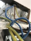
The problem was here:
F6EEB2CC-A80E-4DED-8D16-FCB9093A2950.jpeg

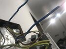
I sleeved the neutral with some spare sleeving I had in he toolbox. Was that the right thing to do?
C13D6274-D575-41E9-8DC7-7CE4ED8A7BA1.jpeg

Repeated the continuity and IR test and everything passed.

Thanks for all your help.
 
Last edited:

DIYnot Local

Staff member

If you need to find a tradesperson to get your job done, please try our local search below, or if you are doing it yourself you can find suppliers local to you.

Select the supplier or trade you require, enter your location to begin your search.


Are you a trade or supplier? You can create your listing free at DIYnot Local

 
Sponsored Links
Back
Top