
You are using an out of date browser. It may not display this or other websites correctly.
You should upgrade or use an alternative browser.
You should upgrade or use an alternative browser.
Lectros Osmotic Damp Proofing System Problem
- Thread starter Poisonata
- Start date
Hi ngonk,
People have made the thread a useful addition to the Lectros installation manual which should save others time. So if you've got anything to add then post away.
People have made the thread a useful addition to the Lectros installation manual which should save others time. So if you've got anything to add then post away.
We come across these systems in old cottages on a regular basis in our area. Usually when rewiring (chasing) or when doing a CU swap. The transformer is always by the CU, a blue metal box with tungsten filament indicator and a test button.
I have to say, I have never really looked into them too much, other than noticing the (usually) red 2.5mm copper/pvc conductor from the positive, and the 2.5mm copper/pvc green/yellow from the negative.
Have always reconnected them when swapping CU's, but they don't half look ugly next to a shiny new CU!
Thank you, Peet. I can make a description of my experience on the LECTROS system and post it. So you or anybody could comment it, which can be useful to somebody.
I can have it done and post it in 2 days. Do you agreed?
You don't need my approval to post here ngonk. Go for it.
Lectrician,
Any chance you could take a picture of what's inside the box next time you come across one and post it up? I was wondering if it's anything different from the modern version of it.
Any chance you could take a picture of what's inside the box next time you come across one and post it up? I was wondering if it's anything different from the modern version of it.
Lectrician,
Any chance you could take a picture of what's inside the box next time you come across one and post it up? I was wondering if it's anything different from the modern version of it.
They are pop-riveted closed unfortunately.
You don't need my approval to post here ngonk. Go for it.[/quote]
Hello Peet, here are some issues about my experience with the LECTROS system
I own an old house in a village located in the south Portugal, whose construction is at ground level. Their thick (60cm) walls are basically constructed with “earth and stones”, and covered with plaster and painted, as almost all the other houses in the village. It showed effects of rising damp and salts on its walls. Some civil work repair was done in 1994.
In October 2010, I ordered the necessary LECTROS parts (anode wire with electrodes, power supply, etc) and installed them, as described in the supplied mounting instructions. The installation of the titanium anode circuit was done together with some walls&floor repair civil works and is in function since then.
A couple of remarks concerning the installation:
1. Connected to the power supply, I installed a digital Miliampere meter, allowing to monitor the electrical current that flows in the loop. This current average value was at start around 25mA, then went to 23mA after 2 months, after that around 27mA and now is 24mA.
It is also varying from until 2mA in some minutes around its average value, but I think that this is due to the fact that the power supply doesn’t have a filter (electrolytic capacitor) and so the digital meter readings, done by a sampling process are subject to variation.
I have made some recordings of the current variations with an oscilloscope, that I can post.
2. The cathode rod was installed in the floor inside of the house, because there are difficulties to install it in the outside. It was made attention to install it as far as possible from the anodes, at a distance of >1,5meters. The earth rod is some 3m long and with its upper part insulated, leaving 0,5m of not insulated tip deep in the ground.
On the period of time from the installation until the present, a couple of moisture measurements have been made on the walls with a GANN moisture meter. It was noticed an overall lowering of the moisture degree, suggesting some drying of the walls, though some wall parts are still showing a somewhat high moisture readings.
Conclusion
Concerning the walls, it is noticeable at some locations, a loosening of the plaster from the base material, suggesting that rising damp is still in action and with its destructive effects! Which is very annoying!
I’m now in doubt if there is something wrong with the method or the efficiency of the system!!
Please comment the above. Does anybody have similar experience? Are these facts normal and what could be its technical explanation?
A very interesting post. There's a lot there so I'll answer by writing bits as they come into my head.
Are the walls covered with gypsum based plaster and modern paint? From the construction you describe it sounds like the house may have relied on pre-cement ie Lime construction (c1900?) as part of its damp control. There's others on here that will answer that better than I will. But sometimes people have introduced problems into an older building by using modern materials. Modern materials prevent the wall from breathing as they were originally intended to.
I take it that the old plaster was removed and replaced after the damp system was installed. The salts in the plaster may have been hygroscopic, attracting water from the atmosphere. So even if the underlying damp problem had been cured this may have continued to be a problem. Again others might offer more on that.
The walls are quite thick and also don't sound to have a cavity. Did you use the deep anodes that Lectros do to enable good coverage of the wall through its thickness? What is the coverage of the anodes in the walls at the moment? What distances are between them? At some point the effect of an anode must diminish and I would think that the rate at which it does depends on wall conditions. I have no solid data for what their spacing should be, only noting that the installation manual says to reduce the distances for problematic walls and that the anodes supplied come on 1M spacings, which I assume to be the maximum distance for average conditions.
The earth rod sounds very deep. 3M is quite long for a rod. But its length is determined by ground conditions, the idea being to ensure that the rod is in permanently conductive ground and that often means that it sits in damp/wet ground and probably has gone into the water table. What are the ground conditions like? How low is the water table below the level of the bottom of the wall? Have you ever tested the effectiveness of the rod?
If you are connecting a mains powered oscilloscope to the the system you may change the system performance and the signals that you're trying to observe. Many oscilloscopes have probe grounds which are connected to the mains earth.
It is interesting to read what currents you have in the system. At the moment I don't have any data on the currents in the systems I have put in, neither are in my house. If I can get such data I will let you know. I would of expected the current to fall to some minimum amount. Seeing your readings makes me wonder has the system done what it can and has now settled to its final value.
Regarding possible current variations in the readings due to an unsmoothed DC supply. I did wonder about the effect of an unsmoothed output when I saw it on the oscilliscope. I would expect the output to change once the system was installed but quite how it would I'm not sure, again if I can, at some point I will scope the output with it connected to the system.
Regarding the sampling of the meter and a possible error due to it. What I think you're referring to there is possible aliasing distortion. Although I would of thought you'd see a fairly regular cyclic variation due to the product and drift of the two frequencies? Different meters measure varying waveforms differently. Once the waveshape becomes non-sinusoidal then things could get quite complex. If you doubt your meter's interpretation you could filter the output to give a more stable reading by putting it through a diode and then to a resistor in parallel with a capacitor . Meter across the capacitor. Pick your time constant to be perhaps 10x the 100Hz of the output ( so about 0.1sec) and drain resistor to be an insignificant load on the system. Depending on where you connect the circuit it would read voltage or current and with a value that was near peak.
The GANN moisture meters and similar have to be used with care. They can be effected by all kinds of things, not just damp. In this instance was the system turned off before you used it? I don't know yet if they're effected by the system when it's on.
It would be interesting to see your oscilloscope results.
Some thoughts on possible ways to investigate the system performance. -
Is it possible, using the earth rod as a reference, to probe voltages in the walls in order to see more of what is going on? Different heights and different locations to build a map?
Possibly add or subtract an anode (or anodes) to see if the change is reflected in the current in the system. Then you'll know if changes are having an effect.
Hi Peet! Thank you very much for tour attention&patience and your time in analysing and commenting so carefully the issues that I wrote.
Are you a Lectros specialist?
I'm Electronic engineer and I know very little about civil construction.
I dont speak very well the English language, but I'll try to reply to your text very soon.
I'll contact very soon.
Are you a Lectros specialist?
I'm Electronic engineer and I know very little about civil construction.
I dont speak very well the English language, but I'll try to reply to your text very soon.
I'll contact very soon.
Most old buildings do rely on walls breathing to keep dampness in the low part of the wall. A coat of vinyl paint can prevent that breathing and raise the dampness higher up the wall.
My 490 year old cottage has very damp walls and I am considering an electrical method to reduce ( but not eliminate ) the amount of moisture that has to breathe out of the wall.
It is apparent that the system has to be designed to suit the type of wall and the amount of damp if best ( acceptable ) results are to be achieved.
The length of the anodes and distance between them depends on the type of stone in the wall and the thickness of the wall. The number of ground rods and their location also has to be considered on the basis of resistance through the ground to the base of the wall along its entire length.
I have looked at http://www.lectros.com/lectros_misc.asp?ID=SYS and it seems to be designed for brick walls where a short anode will suffice. They also supply a long anode but I could not find any mention of how long they are.
I believe for stone walls the anode will need to go most of the way through the wall to ensure the vertical voltage gradient throughout the thickness of the wall.
A very interesting post. There's a lot there so I'll answer by writing bits as they come into my head.
Q - Are the walls covered with gypsum based plaster and modern paint? From the construction you describe it sounds like the house may have relied on pre-cement ie Lime construction (c1900?) as part of its damp control. There's others on here that will answer that better than I will. But sometimes people have introduced problems into an older building by using modern materials. Modern materials prevent the wall from breathing as they were originally intended to.
R – The house was constructed using pre-cement (lime), but t here is no gypsum based plaster. The base structure is in good condition. The more recent walls finish are made with cement mortar plaster and painted with white water based paint. About the materials, care was taken to avoid materials that could make difficult the wall breathing.
Q - I take it that the old plaster was removed and replaced after the damp system was installed. The salts in the plaster may have been hygroscopic, attracting water from the atmosphere. So even if the underlying damp problem had been cured this may have continued to be a problem. Again others might offer more on that.
R – More recently, with the installation of the Lectros system, the old plaster was removed and the walls were cleaned for eliminating remaining salts and replaced with new cement plaster.
Q - The walls are quite thick and also don't sound to have a cavity. Did you use the deep anodes that Lectros do to enable good coverage of the wall through its thickness? What is the coverage of the anodes in the walls at the moment? What distances are between them? At some point the effect of an anode must diminish and I would think that the rate at which it does depends on wall conditions. I have no solid data for what their spacing should be, only noting that the installation manual says to reduce the distances for problematic walls and that the anodes supplied come on 1M spacings, which I assume to be the maximum distance for average conditions.
R - I didn’t use the long anodes because I read in the technical instructions that for thickness up to 60cm the normal anodes would satisfy. However they were placed so as to be in half the walls thickness. The spacing between anodes would result from that condition (<1m).
Q - The earth rod sounds very deep. 3M is quite long for a rod. But its length is determined by ground conditions, the idea being to ensure that the rod is in permanently conductive ground and that often means that it sits in damp/wet ground and probably has gone into the water table. What are the ground conditions like? How low is the water table below the level of the bottom of the wall? Have you ever tested the effectiveness of the rod?
R – 3m is a standard length for the rod we can get here. Difficult to know where is the water table.
How shall I test the effectiveness of the rod?
Anyway, the current readings around 25 mA suggest that the system is operating in good condition.
Q - If you are connecting a mains powered oscilloscope to the system you may change the system performance and the signals that you're trying to observe. Many oscilloscopes have probe grounds which are connected to the mains earth.
R – The oscilloscope I use is a PC oscilloscope that uses 5V supply from the computer’s USB output. I think it is galvanically insulated from earth.
Q - It is interesting to read what currents you have in the system. At the moment I don't have any data on the currents in the systems I have put in, neither are in my house. If I can get such data I will let you know. I would of expected the current to fall to some minimum amount. Seeing your readings makes me wonder has the system done what it can and has now settled to its final value.
R – It is not easy to interpret the results. Anyway I send you pictures of the data obtained with the oscilloscope.
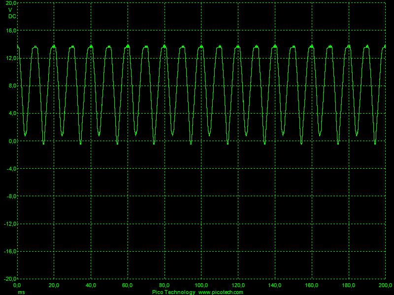
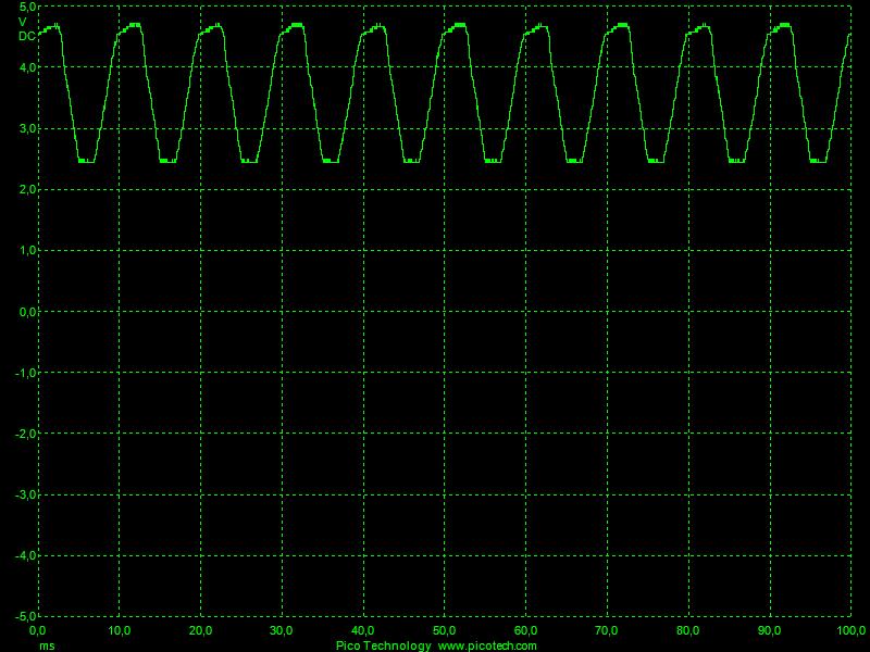
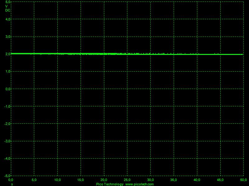
1.gif – Shows the output voltage from the power supply, disconnected from the anodes&catode. It’s a typical full wave rectified voltage (with some 50Hz hum superimposed). 2.png - Voltage between anode and cathode with the system connected. 3.gif – Voltage on the wall when anodes and cathode are disconnected from power supply.
Q - Regarding possible current variations in the readings due to an unsmoothed DC supply. I did wonder about the effect of an unsmoothed output when I saw it on the oscilloscope. I would expect the output to change once the system was installed but quite how it would I'm not sure, again if I can, at some point I will scope the output with it connected to the system.
R – See curves.
Q - Regarding the sampling of the meter and a possible error due to it. What I think you're referring to there is possible aliasing distortion. Although I would of thought you'd see a fairly regular cyclic variation due to the product and drift of the two frequencies? Different meters measure varying waveforms differently. Once the waveshape becomes non-sinusoidal then things could get quite complex. If you doubt your meter's interpretation you could filter the output to give a more stable reading by putting it through a diode and then to a resistor in parallel with a capacitor. Meter across the capacitor. Pick your time constant to be perhaps 10x the 100Hz of the output ( so about 0.1sec) and drain resistor to be an insignificant load on the system. Depending on where you connect the circuit it would read voltage or current and with a value that was near peak.
R – Your comment is correct, though I see some difficulties on using a diode, because the forward voltage would not be attained (the voltage drop in a 1ohm resistor used for current readings is not enough) . However seeing curve 2.png, there is clearly a DC component (2V – this might be the so-called backwall voltage) which is superimposed with an alternate 100Hz component, possibly responsible for the short time variations on the digital meter. I’ll have to study this in more detail.
Q -The GANN moisture meters and similar have to be used with care. They can be effected by all kinds of things, not just damp. In this instance was the system turned off before you used it? I don't know yet if they're effected by the system when it's on.
R – No, the system was on! Good that you thought of it!
I’m going to check this. Thanks for reminding! The Gann system works on the capacitive principle!
Q - It would be interesting to see your oscilloscope results.
R – I’ll send them in annex.
Some thoughts on possible ways to investigate the system performance.
R – GOOD Ideas!
Q - Is it possible, using the earth rod as a reference, to probe voltages in the walls in order to see more of what is going on? Different heights and different locations to build a map?
R – I guess it is possible to connect one probe to the cathode and the other one to some sharp tool to pick up the voltage at the wall and make several readings.
Q - Possibly add or subtract an anode (or anodes) to see if the change is reflected in the current in the system. Then you'll know if changes are having an effect.
R –Difficult to reach the anodes since they are cemented in the walls. However, I think I could make an experiment by connect the end of the titanium circuit to its beginning, closing the loop with low resistance copper wire. This will reduce the resistance of the loop because the titanium is more resistive than the copper.
Q - Are the walls covered with gypsum based plaster and modern paint? From the construction you describe it sounds like the house may have relied on pre-cement ie Lime construction (c1900?) as part of its damp control. There's others on here that will answer that better than I will. But sometimes people have introduced problems into an older building by using modern materials. Modern materials prevent the wall from breathing as they were originally intended to.
R – The house was constructed using pre-cement (lime), but t here is no gypsum based plaster. The base structure is in good condition. The more recent walls finish are made with cement mortar plaster and painted with white water based paint. About the materials, care was taken to avoid materials that could make difficult the wall breathing.
Q - I take it that the old plaster was removed and replaced after the damp system was installed. The salts in the plaster may have been hygroscopic, attracting water from the atmosphere. So even if the underlying damp problem had been cured this may have continued to be a problem. Again others might offer more on that.
R – More recently, with the installation of the Lectros system, the old plaster was removed and the walls were cleaned for eliminating remaining salts and replaced with new cement plaster.
Q - The walls are quite thick and also don't sound to have a cavity. Did you use the deep anodes that Lectros do to enable good coverage of the wall through its thickness? What is the coverage of the anodes in the walls at the moment? What distances are between them? At some point the effect of an anode must diminish and I would think that the rate at which it does depends on wall conditions. I have no solid data for what their spacing should be, only noting that the installation manual says to reduce the distances for problematic walls and that the anodes supplied come on 1M spacings, which I assume to be the maximum distance for average conditions.
R - I didn’t use the long anodes because I read in the technical instructions that for thickness up to 60cm the normal anodes would satisfy. However they were placed so as to be in half the walls thickness. The spacing between anodes would result from that condition (<1m).
Q - The earth rod sounds very deep. 3M is quite long for a rod. But its length is determined by ground conditions, the idea being to ensure that the rod is in permanently conductive ground and that often means that it sits in damp/wet ground and probably has gone into the water table. What are the ground conditions like? How low is the water table below the level of the bottom of the wall? Have you ever tested the effectiveness of the rod?
R – 3m is a standard length for the rod we can get here. Difficult to know where is the water table.
How shall I test the effectiveness of the rod?
Anyway, the current readings around 25 mA suggest that the system is operating in good condition.
Q - If you are connecting a mains powered oscilloscope to the system you may change the system performance and the signals that you're trying to observe. Many oscilloscopes have probe grounds which are connected to the mains earth.
R – The oscilloscope I use is a PC oscilloscope that uses 5V supply from the computer’s USB output. I think it is galvanically insulated from earth.
Q - It is interesting to read what currents you have in the system. At the moment I don't have any data on the currents in the systems I have put in, neither are in my house. If I can get such data I will let you know. I would of expected the current to fall to some minimum amount. Seeing your readings makes me wonder has the system done what it can and has now settled to its final value.
R – It is not easy to interpret the results. Anyway I send you pictures of the data obtained with the oscilloscope.
1.gif – Shows the output voltage from the power supply, disconnected from the anodes&catode. It’s a typical full wave rectified voltage (with some 50Hz hum superimposed). 2.png - Voltage between anode and cathode with the system connected. 3.gif – Voltage on the wall when anodes and cathode are disconnected from power supply.
Q - Regarding possible current variations in the readings due to an unsmoothed DC supply. I did wonder about the effect of an unsmoothed output when I saw it on the oscilloscope. I would expect the output to change once the system was installed but quite how it would I'm not sure, again if I can, at some point I will scope the output with it connected to the system.
R – See curves.
Q - Regarding the sampling of the meter and a possible error due to it. What I think you're referring to there is possible aliasing distortion. Although I would of thought you'd see a fairly regular cyclic variation due to the product and drift of the two frequencies? Different meters measure varying waveforms differently. Once the waveshape becomes non-sinusoidal then things could get quite complex. If you doubt your meter's interpretation you could filter the output to give a more stable reading by putting it through a diode and then to a resistor in parallel with a capacitor. Meter across the capacitor. Pick your time constant to be perhaps 10x the 100Hz of the output ( so about 0.1sec) and drain resistor to be an insignificant load on the system. Depending on where you connect the circuit it would read voltage or current and with a value that was near peak.
R – Your comment is correct, though I see some difficulties on using a diode, because the forward voltage would not be attained (the voltage drop in a 1ohm resistor used for current readings is not enough) . However seeing curve 2.png, there is clearly a DC component (2V – this might be the so-called backwall voltage) which is superimposed with an alternate 100Hz component, possibly responsible for the short time variations on the digital meter. I’ll have to study this in more detail.
Q -The GANN moisture meters and similar have to be used with care. They can be effected by all kinds of things, not just damp. In this instance was the system turned off before you used it? I don't know yet if they're effected by the system when it's on.
R – No, the system was on! Good that you thought of it!
I’m going to check this. Thanks for reminding! The Gann system works on the capacitive principle!
Q - It would be interesting to see your oscilloscope results.
R – I’ll send them in annex.
Some thoughts on possible ways to investigate the system performance.
R – GOOD Ideas!
Q - Is it possible, using the earth rod as a reference, to probe voltages in the walls in order to see more of what is going on? Different heights and different locations to build a map?
R – I guess it is possible to connect one probe to the cathode and the other one to some sharp tool to pick up the voltage at the wall and make several readings.
Q - Possibly add or subtract an anode (or anodes) to see if the change is reflected in the current in the system. Then you'll know if changes are having an effect.
R –Difficult to reach the anodes since they are cemented in the walls. However, I think I could make an experiment by connect the end of the titanium circuit to its beginning, closing the loop with low resistance copper wire. This will reduce the resistance of the loop because the titanium is more resistive than the copper.
I think we have two lines going here. Firstly the original & main thread of 'do you have a damp problem'. And secondly, an interesting discussion on what we actually see in an operating Lectros system.
The cement based plaster/render will also most likely reduce the walls ability to breathe.
In order to try to establish more about what's going on a page that you may find quite useful is
http://www.mill-rise.freeserve.co.uk/Contents.htm
Graham Coleman's website I have found most helpful over the years. Well worth a read. Although not directly applicable I would also recommend that you read the section 'The Facts about Chemical dpcs and Replastering' for an interesting insight into salt distribution in walls. From what I read of the tests for salts and free water in the wall they make good sense to me but I have experience of them.
From what I know the unwanted water in walls seems to be a balance between many things. Height of standing water or water table, construction & coatings, barriers in the wall such as an effective DPC and many other things. All together they can mean the difference between something that's acceptable or unacceptable. Which is why the subject often leads to a lot of discussion and controversy.
The page
http://www.palgrave-journals.com/jba/journal/v6/n1/full/jba201013a.html
from another thread on DIYNOT is also another interesting read with test data to support its findings.
So you would have anodes spaced at 40cm if I'm correct. From what I've seen of the system and the long anodes that's all they are, they're just regular ones buried deeper. 40cm spacing sounds acceptable although I have no comparative data to compare this to.
Looking back on the posts the only time you mention the effects of the damp after the remedial work was to say 'Concerning the walls, it is noticeable at some locations, a loosening of the plaster from the base material, suggesting that rising damp is still in action'. Is it possible that this is due to other effects? I'm not saying that the walls are not damp but wondering is this down to damp itself?
Providing that the only return path for the current is through the Lectros system's rod then yes I would agree that the current flowing verifies the existence of a connection to the rod.
Maybe worth checking that so that you can rely on the results you have. With all the gear setup see if you have a short between mains earth and the probe ground. If the PC scope runs off a battery driven laptop then this potential grounding issue should go. Galvanic isolation in PC connected test gear is most desirable incase of a fault somewhere or unforeseen grounding issues causing damage to the PC.
I see very similar on the power supplies I have dealt with. Off load the 100hz rectified sine wave would peak at about the 17volt mark I mentioned.
I will drag the scope to the system eventually and record some waveforms for comparison. Before that I need to fix its disk drive and also confirm that its isolators are fully functional.
Closing the loop in this way I would say will have no effect whatsoever. Even moderate amounts of loop resistance (hundreds of ohms) I doubt would effect it. Don't forget that there's a couple of hundred ohms or so in the output of the power supply. As the power supply resistance rises then at some point the system would 'lose its headroom' for operation, in a similar way that a current source would lose its compliance.
'The house was constructed using pre-cement (lime), but there is no gypsum based plaster. The base structure is in good condition. The more recent walls finish are made with cement mortar plaster and painted with white water based paint. About the materials, care was taken to avoid materials that could make difficult the wall breathing.'
The cement based plaster/render will also most likely reduce the walls ability to breathe.
In order to try to establish more about what's going on a page that you may find quite useful is
http://www.mill-rise.freeserve.co.uk/Contents.htm
Graham Coleman's website I have found most helpful over the years. Well worth a read. Although not directly applicable I would also recommend that you read the section 'The Facts about Chemical dpcs and Replastering' for an interesting insight into salt distribution in walls. From what I read of the tests for salts and free water in the wall they make good sense to me but I have experience of them.
From what I know the unwanted water in walls seems to be a balance between many things. Height of standing water or water table, construction & coatings, barriers in the wall such as an effective DPC and many other things. All together they can mean the difference between something that's acceptable or unacceptable. Which is why the subject often leads to a lot of discussion and controversy.
The page
http://www.palgrave-journals.com/jba/journal/v6/n1/full/jba201013a.html
from another thread on DIYNOT is also another interesting read with test data to support its findings.
'I didn’t use the long anodes because I read in the technical instructions that for thickness up to 60cm the normal anodes would satisfy. However they were placed so as to be in half the walls thickness. The spacing between anodes would result from that condition (<1m).'
So you would have anodes spaced at 40cm if I'm correct. From what I've seen of the system and the long anodes that's all they are, they're just regular ones buried deeper. 40cm spacing sounds acceptable although I have no comparative data to compare this to.
Looking back on the posts the only time you mention the effects of the damp after the remedial work was to say 'Concerning the walls, it is noticeable at some locations, a loosening of the plaster from the base material, suggesting that rising damp is still in action'. Is it possible that this is due to other effects? I'm not saying that the walls are not damp but wondering is this down to damp itself?
'How shall I test the effectiveness of the rod? Anyway, the current readings around 25 mA suggest that the system is operating in good condition.'
Providing that the only return path for the current is through the Lectros system's rod then yes I would agree that the current flowing verifies the existence of a connection to the rod.
'The oscilloscope I use is a PC oscilloscope that uses 5V supply from the computer’s USB output. I think it is galvanically insulated from earth.'
Maybe worth checking that so that you can rely on the results you have. With all the gear setup see if you have a short between mains earth and the probe ground. If the PC scope runs off a battery driven laptop then this potential grounding issue should go. Galvanic isolation in PC connected test gear is most desirable incase of a fault somewhere or unforeseen grounding issues causing damage to the PC.
1.gif Shows the output voltage from the power supply
I see very similar on the power supplies I have dealt with. Off load the 100hz rectified sine wave would peak at about the 17volt mark I mentioned.
I will drag the scope to the system eventually and record some waveforms for comparison. Before that I need to fix its disk drive and also confirm that its isolators are fully functional.
'Difficult to reach the anodes since they are cemented in the walls. However, I think I could make an experiment by connect the end of the titanium circuit to its beginning, closing the loop with low resistance copper wire. This will reduce the resistance of the loop because the titanium is more resistive than the copper.'
Closing the loop in this way I would say will have no effect whatsoever. Even moderate amounts of loop resistance (hundreds of ohms) I doubt would effect it. Don't forget that there's a couple of hundred ohms or so in the output of the power supply. As the power supply resistance rises then at some point the system would 'lose its headroom' for operation, in a similar way that a current source would lose its compliance.
- Joined
- 20 Sep 2013
- Messages
- 1
- Reaction score
- 0
- Country

I am amazed to see that people here are actually discussing electro osmosis just like as if it were a method that actually worked.
The electro osmosis scammers have carried on with their fraud for around 50 years, tricking billions of pounds out of millions of naive, stupid customers.
This is what the Building Research Establishment has to say about electro-osmosis:
"There are two types: active and passive; neither has been approved by a recognised laboratory. By far the greater number of systems are of the passive kind, where there is no external source of electricity. They have always been something of a controversial issue. On theoretical grounds, it remains a mystery as to how they can work; their effectiveness has not been demonstrated in the laboratory and field evidence is disappointing.
Active electro-osmotic systems use an external source of electricity. BRE has no evidence to suggest that the two types behave differently in practice, though some of the active systems may be rather susceptible to the effects of mechanical damage and electrochemical corrosion...
Well, they were, a bit over a year ago - I've seen no mention sinceI am amazed to see that people here are actually discussing electro osmosis ....
")
Kind Regards, John
DIYnot Local
Staff member
If you need to find a tradesperson to get your job done, please try our local search below, or if you are doing it yourself you can find suppliers local to you.
Select the supplier or trade you require, enter your location to begin your search.
Please select a service and enter a location to continue...
Are you a trade or supplier? You can create your listing free at DIYnot Local