• Looking for a smarter way to manage your heating this winter? We’ve been testing the new Aqara Radiator Thermostat W600 to see how quiet, accurate and easy it is to use around the home. Click here read our review.

Logic Puzzle (incorrectly wired 2-way switch)

Joined
7 Oct 2006
Messages
60
Reaction score
0
Location
Manchester
Country
United Kingdom
Hi all,

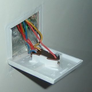
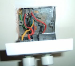
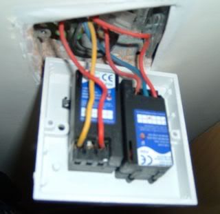
Just wondering if anybody has any ideas on my wiring problem - a previous occupier has incorrectly wired the light switches in the lounge. There is a single switch at one side of the room, and a double (dimmer) switch at the other side. However there doesn't seem to be any consistency with the wall and ceiling lights...

Here's what I mean: -

[code:1]
Single Double Wall Ceiling
A B
Off Off Off Off Off
Off Off On On Off
Off On Off Off On
Off On On On On
On Off Off Off On
On Off On Off Off
On On Off Off On
On On On On On
[/code:1]

I'm assuming that the double switch should turn on the ceiling light and the wall light separately, and the other switch is a two-way for the ceiling.

Any ideas on where I should start? I have read up on two-way switches but I can't work it out...

Thanks in advance...
 
I'm just about to pack up for the night, but if you could get some photos showing how the switches are wired then perhaps tomorrow someone may be able to help. :)
 
Might be wrong but it looks like the single swich is a 2-way in conjunction with dimmer a controlling the ceiling light & dimmer b is controlling the wall light
 
Without actually seeing the wiring it should look something like this:
Dimmer B: red on C (common)
black on L1
That's a one-way wiring to wall light

Dimmer A: red on L1, blue on L2, yellow on C

Single switch: 2-reds in L1, black/blue in L2, yellow in C

Can you check and let me know what you see?
 
Thanks everybody so far,

I've had a look and taken some pictures....

single_switch.jpg


double_dimmer_2.jpg


double_dimmer_1.jpg


Here's how they are wired: -

Single Switch
Common - Red
Other - Red & Yellow
Other - Red & Blue

Double Dimmer Switch
Switch A
L1 - Yellow
L2 - None
C - Red

Switch B
L1 - Red
L2 - Blue
C - Red

Any advice gratefully received...
 
That first piccy. The twin red - that should be split so one goes to L1 & the other to L2. IE one red & the yellow in one terminal & the other red & the blue in the other terminal.

The red at the top is OK providing a) it belongs to the cable with the yellow & blue & b) the red of the 3 core also appears at the common on the other switch.
 
Think the dimmer with the red/red/blue should have the red/yellow/blue belonging to one cable (with the red in C & the yellow & blue in L1 & L2).

The other switch has two reds (belonging to one cable??) One to C & one to L1 (or L2 in this case being a dimmer it does not matter).

Before you move anything, make a note of how it was, then if you get in a big pickle, you can at least return it to how it was before you changed things around.
 
I think all you need do is to take the blue wire out of L2 on switch B and put it in L2 of switch A. :)
 
securespark said:
That first piccy. The twin red - that should be split so one goes to L1 & the other to L2. IE one red & the yellow in one terminal & the other red & the blue in the other terminal.

After looking again in the light of what luminaire has said, my eyes might have been decieving me...

On second look, there may be one red in each of the lower terminals of the rocker switch. I thought both reds were in one terminal.

However, its worth checking the rest of what I mentioned to make sure the conductors from each corresponding cable have not been mixed up:

Oh, and I omitted the fact that the two reds will be from different cables, because there are neutrals at the switch position.
 
luminaire said:
I think all you need do is to take the blue wire out of L2 on switch B and put it in L2 of switch A. :)

Thanks - I've just tried this but things still aren't right. The double switch now seems to operate the lights correctly, but the single switch doesn't do anything at all (although lights flicker when operated) - whether the single's on or off, the double switch can turn on and off both lights.

Any other ideas?

Thanks again....
 
We need to know exactly which wires belong to which cables in each switch:

EG: there is a twin red in switch A and the wires are attached to common & L1 of the left hand dimmer switch etc......

I know you've told us which colour conductors are in which terminals, but we need to know which cables they come from too.

Maybe if you could post some more pix, this time showing the cables as they enter the switch boxes.
 
OK, here goes: -

Single Switch
Common - Red Wire Q
Other - Red Wire P & Yellow Wire Q
Other - Red Wire P & Blue Wire Q

Double Dimmer Switch
Switch A
L1 - Yellow Wire Z
L2 - None
C - Red Wire X

Switch B
L1 - Red Wire Y
L2 - Blue Wire Z
C - Red Wire Z

Hopefully this explains which wires go into the same cable. It's a bit hard to take photos as it's hard to see what wire goes where....
 
Seems like you should swop red Y & yellow Z over as securespark said earlier.
 
Well, I've drawn out a diagram of what I think happens, but to be certain you will need to get hold of a multimeter and use the voltage setting & continuity settings to ascertain what is connected to what.

I Think:

Wire Q (Red, yellow & Blue cores) links the single rockerswitch box to the double dimmer switch box. (At the dimmer end you call it Wire Z) This will give two way switching for whatever light wire P controls.

From your latest description, the wiring in the single switch is correct.

Wire Z should be connected to Common L1 & L2 of one of the dimmer modules. This should give you two way switching.

Are Wires X & Y two single conductors?

I think they should be connected to the terminals of the other dimmer module, one to Common, one to L1.

I think you have said that you have tried this & it does not work. If this is the case, please recheck all connections. If it still does not work:

Disconnect all wires from all terminals, first noting where there are now. Leave the neutrals in the seperate block as they are.

With the power OFF, short together the blue & yellow of the 3 core at one end & check with continuity setting you get a buzz across blue/yellow at the other end. This proves that those ends belong to the same cable.

Now put a choc block on the end of each wire. Turn the power back on & test with the voltage setting (set to 400V) against earth to find out which conductors are live.

Then turn the power off, and connect together the cores of wire P.

Then connect wire x to wire y. Then reinstate the power. What happens?

Report back!!
 

If you need to find a tradesperson to get your job done, please try our local search below, or if you are doing it yourself you can find suppliers local to you.

Select the supplier or trade you require, enter your location to begin your search.


Are you a trade or supplier? You can create your listing free at DIYnot Local

 
Back
Top